Natural laminar flow aerofoil profile with high lift

A laminar flow wing and high-lift technology, applied in wing design and aircraft field, can solve problems such as flow separation, large lift coefficient, and small laminar flow area on the airfoil surface

Inactive Publication Date: 2016-05-11
XIAN AIRCRAFT DESIGN INST OF AVIATION IND OF CHINA
View PDF6 Cites 18 Cited by
  • Summary
  • Abstract
  • Description
  • Claims
  • Application Information

AI Technical Summary

Problems solved by technology

[0002] Conventional natural laminar flow airfoil, in order to ensure sufficient laminar flow area and laminar flow stability, the upper surface of the airfoil is designed according to the forward pressure gradient, the peak suction force is behind, and the suction force at the front of the airfoil is small, resulting in the work of the airfoil The lift coefficient is small; the maximum thickness of the airfoil is at the rear, and the reverse pressure gradient at the rear of the airfoil is relatively large. In the

Method used


Image

  • Natural laminar flow aerofoil profile with high lift
  • Natural laminar flow aerofoil profile with high lift
  • Natural laminar flow aerofoil profile with high lift

Examples


Embodiment Construction

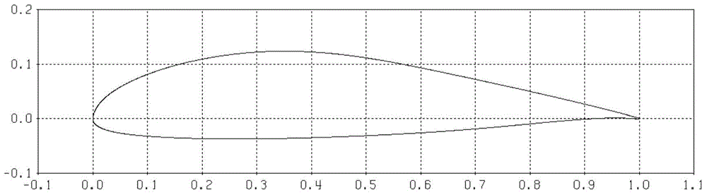
[0017] A high-lift natural laminar flow airfoil is characterized in that the airfoil has a streamlined structure with a blunt leading edge and a weakly reversed trailing edge, and the surface curve of the airfoil is geometrically single-convex without obvious curvature inflection.

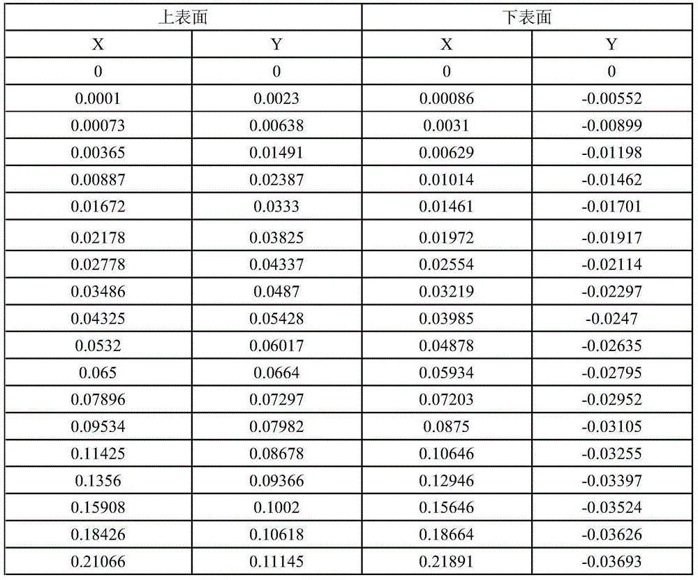
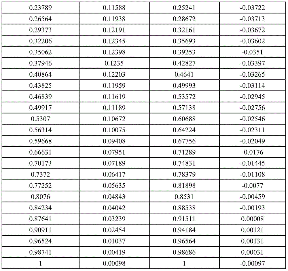
[0018] High-lift natural laminar flow airfoil, its geometric coordinates Table 1 reflects, and refer to the attached figure 1 :

[0019] Table 1

[0020]

[0021]

[0022] The airfoil of the present invention, under free transition conditions, the lift-to-drag ratio corresponding to the design lift coefficient (CL=1.1) is about 125, and the maximum lift-to-drag ratio is about 130; while the conventional turbulent airfoil is at the design lift coefficient (CL=1.1) The lift-to-drag ratio is only about 60.

[0023] The design lift coefficient of the conventional natural laminar flow airfoil is small (generally less than 0.5). In the state of high lift coefficient, the laminar flow region and t...


PUM


Abstract

The invention provides a natural laminar flow aerofoil profile with high lift. The natural laminar flow aerofoil profile is characterized in that the aerofoil profile is of a streamlined structure with a blunt-end leading edge and a weakly recurved trailing edge and the surface curve of the aerofoil profile is simply geometrically convex and is free of obvious curvature and inflection.

Description

technical field [0001] The invention relates to the field of aircraft technology, especially the field of wing design. Background technique [0002] Conventional natural laminar flow airfoil, in order to ensure sufficient laminar flow area and laminar flow stability, the upper surface of the airfoil is designed according to the forward pressure gradient, the peak suction force is behind, and the suction force at the front of the airfoil is small, resulting in the work of the airfoil The lift coefficient is relatively small; the maximum thickness of the airfoil is at the rear, and the reverse pressure gradient at the rear of the airfoil is relatively large. In the state of high lift, the laminar flow area and the laminar flow stability will be reduced, which will easily cause laminar flow transition and flow separation. [0003] The conventional high-lift airfoil is designed with blunt leading edge, large leading edge camber and large trailing edge camber. The airfoil has a l...

Claims


Application Information

Patent Timeline
IPC IPC(8): B64C3/14
Inventor 李权冯海勇雷武涛张彦军
Owner XIAN AIRCRAFT DESIGN INST OF AVIATION IND OF CHINA
Why Eureka
Try Eureka