Passenger conveying device

A technology of passenger conveying and driving device, which is applied in transportation and packaging, escalators, etc., to reduce the number of parts and improve the set-up.

Inactive Publication Date: 2016-05-11
HITACHI LTD +1
View PDF12 Cites 0 Cited by
  • Summary
  • Abstract
  • Description
  • Claims
  • Application Information

AI Technical Summary

Problems solved by technology

In addition, in the technology described in this patent document 1, a gear motor is installed between a pair of step

Method used


Image

  • Passenger conveying device
  • Passenger conveying device
  • Passenger conveying device

Examples


Example Embodiment

[0023] [Example 1]

[0024] Such as Figure 4 As shown, a passenger conveying device, such as an escalator, includes: a step 1, which is connected in an endless shape and moves between the upper and lower openings; a step driver 3, which is arranged in the upper machine room 2; and a drive chain gear 4 , The drive sprocket 4 is driven by a step drive 3; and a step chain 5, which is wound and suspended on the drive sprocket 4. In addition, the step drive device A is constituted by the step drive 3, the drive sprocket 4, and the step chain 5. The power of the motor of the step drive 3 is transmitted to the step 1 via the drive sprocket 4 and the step chain 5, and the step 1 is at the upper and lower ports Move between.

[0025] In addition, a railing 6 and a handrail 7 are included. The railing 6 is erected on the side along the traveling direction of the step 1. The handrail 7 is supported by the railing 6 and moves in the same direction as the step 1.

[0026] Moreover, in Embodime...

Example Embodiment

[0032] [Example 2]

[0033] Here, based on Figure 5 to Figure 8 The second embodiment of the passenger conveyor according to the present invention will be described. In addition, the same reference numerals are given to the same structures as those shown in the first embodiment.

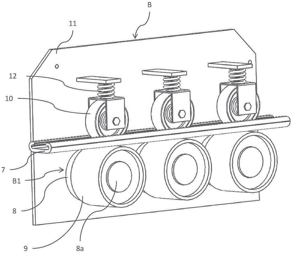
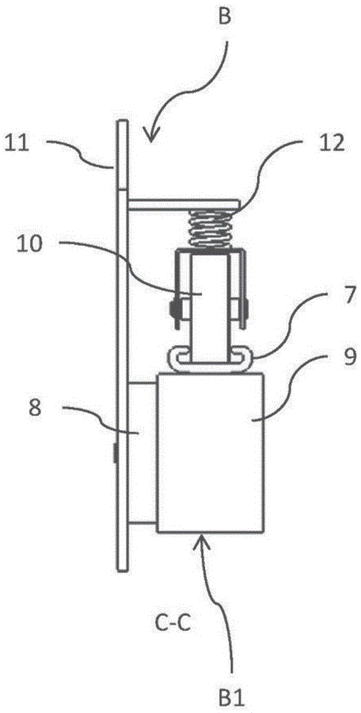
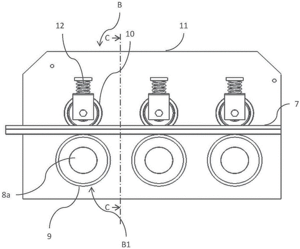
[0034] In Embodiment 2, the difference from Embodiment 1 described above is that Figure 5 to Figure 8 As shown, on the reverse fixed side of the outer rotor type electric motor 8, a bearing 13 supporting the output shaft 8a of the outer rotor type electric motor 8 is provided. The bracket 14 fixed to the frame material 11 at both ends includes the bearing 13.

[0035] According to the second embodiment, by holding both ends of the output shaft 8a of the outer rotor type electric motor 8, the performance map improves the robustness.


PUM


Abstract

The invention provides a passenger conveying device which can drive a handle through a simple structure. The device comprises a handle (7), which is connected to be shaped like no end and moves between an upper opening and a lower opening in a direction the same as a step; a handle drive apparatus (B) which is provided with a drive roller (9) and a crimping roller (10). The drive roller (9) is driven by a drive unit to abut against one surface of the handle (7). The crimping roller (10) is disposed at a position opposite to the drive roller (9), and abuts against the other surface of the handle (7). The device employs the drive roller (9) and the crimping roller (10) to clamp and drive the handle (7). In the device, the drive unit is set as an external rotor type motor (8), and is set as the following drive unit (B1). The following drive unit (B1) enables the drive roller (9) to be installed on an output shaft (8a) of the external rotor type motor (8), and directly drive the drive roller (9) to move through the external rotor type motor (8).

Description

technical field [0001] The invention relates to a passenger conveying device. Background technique [0002] Generally speaking, the power generated by the motor of the step driving device that drives the steps that are connected endlessly and moves between the upper and lower openings is also transmitted to the handrail driving device that drives the handrail synchronously with the steps. In contrast to this, there is also proposed a passenger conveyor in which the motor of the step driving device and the motor of the handrail driving device are separately provided as in Patent Document 1. [0003] The handrail driving device described in Patent Document 1 includes: a speed reducer composed of planetary gears; and a gear motor integrally formed with a motor mounted on the frame of the speed reducer; There is a drive chain that rotates the drive roller and crimp roller. Then, the rotation of the motor is decelerated by the speed reducer, and the drive roller is rotationally...

Claims


Application Information

Patent Timeline
IPC IPC(8): B66B23/04
Inventor 福田敏行上田雅司山下智典坂上充
Owner HITACHI LTD
Why Eureka
Try Eureka