Rotary magneto-rheological damper

A magneto-rheological damper, rotary technology, applied in the direction of non-rotational vibration suppression, shock absorber, shock absorber, etc., can solve the problems of small maximum damping force, difficult sealing, few patents, etc., to achieve adjustable The effect of damping force, large damping force and reliable performance

Active Publication Date: 2016-05-11
ZHUZHOU TIMES NEW MATERIALS TECH
View PDF16 Cites 12 Cited by
  • Summary
  • Abstract
  • Description
  • Claims
  • Application Information

AI Technical Summary

Problems solved by technology

However, so far, it is mainly concentrated in the field of the traditional damper structure of the straight cylinder damper, and there are not many researches and patents on the relatively special-shaped magneto-rheological damper.
Such as application number: 01113723 patent, 201110240664 patent, 201210509450 patent, they all have a common feature of using a built-in magnetic circuit, the advantage of this design is to avoid the complex structure of difficult sealing, the disadvantage is the magnetic field strength of the built-in magnetic circuit The maximum damping force value that can be provided by low is very small
Domestic magnetorheological dampers are at a backward stage in terms of structural engineering. The reason is that domestic rotary magnetorheological dampers mainly face the following two problems at this stage: First, the magnetic flow that can provide a large damping force The research and development of variable dampers is very difficult; second, magnetorheological dampers should have good reliability and sealing performance, which requires high manufacturing process

Method used


Image

  • Rotary magneto-rheological damper
  • Rotary magneto-rheological damper
  • Rotary magneto-rheological damper

Examples


specific Embodiment approach

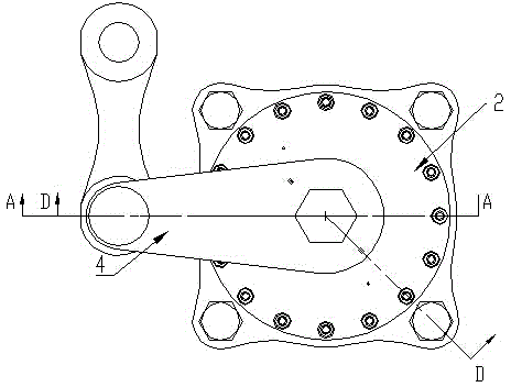
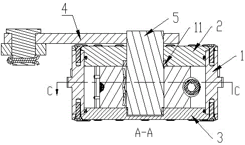
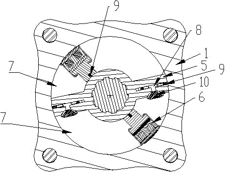
[0024] A rotary magneto-rheological damper, including a cylinder 1, an upper end cover 2, a lower end cover 3, a stator 4, a rotor blade 5, a magnetic circuit 6 and a rocker arm connected to the stator outside the upper end cover 2, and upper and lower end covers 2.3. The stator 4 and the cylinder 1 are sealed with a static seal O-ring. The upper end cover 2 is provided with wire holes and exhaust holes. The rotor blade 5 can rotate around the stator 4. The rotor blade 5 is connected to the upper end. The cover 2 and the lower end cover 3 are dynamic seals, which divide the cylinder body into two sealed spaces 7, and the magnetic circuit 6 is respectively arranged in the two sealed spaces 7, and is dynamically sealed with the root of the rotor blade 5 and the cylinder barrel 1, and is connected with the upper and lower end covers 2, 3 fixed seal. The sealing of upper and lower end covers 2, 3, stator 4 and cylinder 1 adopts static sealing O-rings. The dynamic sealing between ...


PUM


Abstract

The invention discloses a rotary magneto-rheological damper and belongs to electronic devices. The rotary magneto-rheological damper comprises a cylinder barrel, an upper end cover, a lower end cover, a stator, a rotor blade, a magnetic circuit and a rocker arm. The portion, outside the upper end cover, of the rocker arm is connected with the stator. The upper end cover, the lower end cover, the stator and the cylinder barrel are sealed. Wire holes and exhaust holes are formed in the upper end cover. The rotor blade can rotate around the stator and is in motive sealing with the upper end cover and the lower end cover to divide a cylinder body into two sealed spaces. The magnetic circuit is arranged in the two sealed spaces. The magnetic circuit is in motive sealing with the root of the rotor blade and the cylinder barrel and is in fixed sealing with the upper end cover and the lower end cover. The rotary magneto-rheological damper can provide large damping force, the damping force can be adjusted in real time, and the weight is lower relatively.

Description

technical field [0001] The invention relates to electronic devices, in particular to a rotary adjustable damping magnetorheological damper using magnetorheological fluid as a medium. Background technique [0002] At present, commonly used rotary dampers are generally made of the principle of rotary springs or oil pressure valves. The damping force of the rotary spring is generally not adjustable or the adjustable range is very small, and the maximum damping force value that can be provided is very small. The damping force of the hydraulic valve type rotary damper is also not adjustable or the adjustable range is very small, and when it wants to obtain a large damping force, the structure will be very huge and bulky. Commonly used rotary dampers need to be designed for different stress conditions in order to achieve the optimal vibration reduction effect, and cannot cope with vibration under complex conditions. The magnetorheological damper is a semi-active damper based on t...

Claims


Application Information

Patent Timeline
Patent Type & Authority Applications(China)
IPC IPC(8): F16F9/53F16F9/36
Inventor 王里达涂奉臣贺才春胡小刚沈绍伟
Owner ZHUZHOU TIMES NEW MATERIALS TECH
Why Eureka
Try Eureka