Manual safety device based on driving hammer type emission pistol

A safety device and hammer technology, which is applied in the field of firearms, can solve the problem of single safety status of pistols, and achieve the effects of fewer parts used, improved safety, and small installation space

Active Publication Date: 2016-05-11
CHONGQING JIANSHE IND GRP
8 Cites 4 Cited by

AI-Extracted Technical Summary

Problems solved by technology

[0002] At present, there are no pistols with both manual safety and cocking release functions in China. The hammer-type firing mechanism pistol with manual safety has a single ...

Abstract

The invention discloses a manual safety device based on a driving hammer type emission pistol. The manual safety device comprises a manual safety device body, stop iron, a driving hammer, a driving hammer spring, a driving hammer spring rod, a driving hammer spring base, an emission machine base and a stop iron spring; the emission machine base is fixedly installed on a grip of the pistol, the manual safety device body is installed on the emission machine base and can rotate, a first shaft and a second shaft are fixedly installed on the emission machine base, the stop iron capable of rotating and the stop iron spring are installed on the first shaft in a sleeving mode, and the driving hammer and the driving hammer spring base are installed on the second shaft in a sleeving mode; the driving hammer spring rod is arranged in the driving hammer, the driving hammer spring is installed on the driving hammer spring rod in a sleeving mode, the rear end of the driving hammer spring base abuts against the driving hammer spring rod, and the front end of the driving hammer spring base is matched with the manual safety device body; the stop iron is matched with the manual safety device body and the driving hammer. The stop iron and the driving hammer can be controlled by rotating the manual safety device body, the safety function can be realized, the driving hammer can be safely relieved at the single-action to-be-percussed state, and the safety of the pistol can be improved further.

Application Domain

Technology Topic

Image

  • Manual safety device based on driving hammer type emission pistol
  • Manual safety device based on driving hammer type emission pistol
  • Manual safety device based on driving hammer type emission pistol

Examples

  • Experimental program(1)

Example Embodiment

[0045] The present invention will be further described below with reference to the drawings and embodiments.
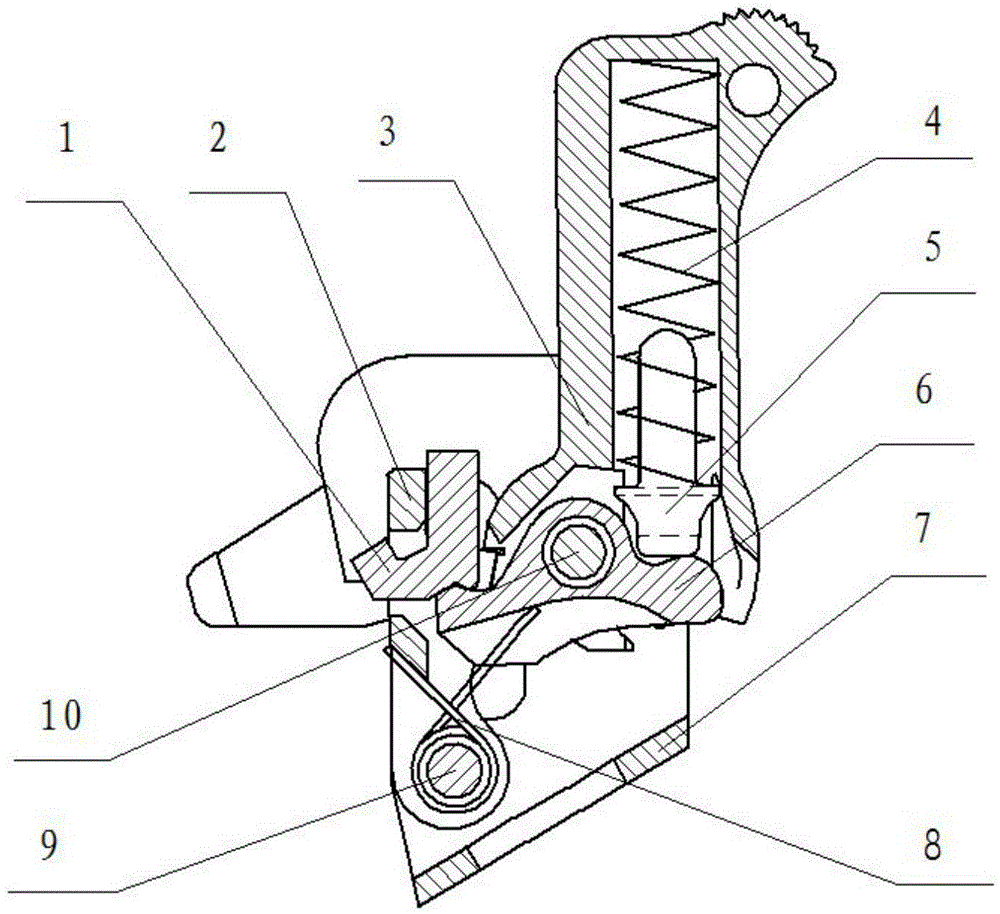
[0046] Such as figure 1 As shown, a manual safety device based on a hammer-type firing pistol includes manual safety 1, iron block 2, hammer 3, hammer spring 4, hammer spring rod 5, hammer spring seat 6, and transmitter seat 7 , Barrier spring 8, the first shaft 9, the second shaft 10. Such as Picture 12 As shown, the transmitter base 7 is roughly U-shaped, and it is fixedly installed on the pistol grip. The two side walls of the transmitter base 7 are symmetrically provided with safety mounting holes 701. A relief hole 702 is also symmetrically provided, and the relief hole 702 is located below the safety mounting hole 701, and the lower part of the safety mounting hole 701 is provided with a gap communicating with the relief hole 702. A first shaft 9 and a second shaft 10 are fixedly arranged between the two side walls of the transmitter base 7, and the first shaft 9 is located at the bottom left of the second shaft 10 and below the relief hole 702 .
[0047] A manual fuse 1 is installed in the fuse mounting hole 701 on the transmitter base. The manual insurance 1 includes left and right wrenches and a limit shaft connecting the left and right wrenches. The left and right wrenches of the manual fuse 1 are respectively located on the outer sides of the two side walls of the transmitter base 7 for rotating the limit shaft of the manual fuse 1, and the two ends of the limit shaft on the manual fuse 1 extend from the transmitter base The gap between the upper relief hole 702 and the fuse mounting hole 701 is inserted into the fuse mounting hole 701 on the transmitter base, and the manual fuse 1 can be rotated in the fuse mounting hole 701. Such as Figure 7a-Figure 7d As shown, the middle section of the limit shaft of the manual insurance 1 is provided with inclined surfaces 105 at the front and rear. The upper part of the middle section of the limit shaft on the manual insurance 1 is provided with a barrier release tooth 102, and the barrier release tooth 102 is located above the inclined surface 105. The lower part of the middle section of the limit shaft on the manual safety 1 is provided with a hook limit portion 106 that is roughly hook-shaped. The rear end of the lower part of the hook limit portion 106 is provided with a safety positioning groove 103 with a certain taper. The front end of the lower part of the hook limit portion 106 is bent backward to form an iron-proof safety tooth 101, which is separated from the front end slope 105 on the manual safety limit shaft; manual safety 1 is on the limit shaft A hammer limiting tooth 104 is provided on the left side of the hook limiting portion, and an interval distance is provided between the hammer limiting tooth 104 and the hook limiting portion 106.
[0048] A rotatable barrier 2 is sleeved on the first shaft 9. Such as figure 2 , Figure 3a , Figure 3b , Figure 8a , Figure 8b , Figure 8c As shown, the iron barrier 2 includes left and right connecting parts sleeved on the first shaft 9, and the upper front ends of the left and right connecting parts are provided with iron barrier stops engaging with the iron barrier safety teeth 101 on the manual insurance. Teeth 201, the upper rear ends of the left and right connecting parts are provided with iron blocking teeth 202 for limiting the position of the hammer 3. The upper ends of the left and right connecting parts of the barrier 2 are located below the limiting shaft on the manual safety 1.
[0049] A connecting portion 204 is provided between the left and right connecting portions of the iron barrier 2, and the connecting portion 204 is located below the iron barrier tooth 202 on the iron barrier, and a space is provided between the connecting portion 204 and the iron barrier tooth 202 Slot 205, the hook limiting portion 106 on the manual insurance passes forward through the relief slot 205 on the barrier iron and can rotate around the barrier iron tooth 202. The outer side of the left side connecting part of the barrier 2 is also provided with a tubular limit part 206 that is in contact with the left side wall of the transmitter base 7 to limit the position.
[0050] The first shaft 9 is also sleeved with an iron iron spring 8 which provides a clockwise rotation force for the iron iron 2, and the iron iron spring 8 is located between the left and right connecting parts of the iron iron and is located in the iron iron Below the connecting portion 204 on the spring seat. The anti-iron spring 8 is a torsion spring. One end of the anti-iron spring 8 is fixed on the anti-iron 2 and the other end of the anti-iron spring 8 is fixed on the hammer spring seat 6.
[0051] A rotatable hammer spring seat 6 and a hammer 3 are sleeved on the second shaft 10.
[0052] Such as Figure 9a , Figure 9b , Figure 9c As shown, the hammer 3 is roughly a rectangular block, the lower end of the hammer 3 is sleeved on the second shaft 10, the lower end of the hammer 3 is provided with a cylindrical limit part, and the center line of the cylindrical limit part is vertical On the two side walls of the transmitter base 7. A limiting groove 306 is formed on the cylindrical limiting portion along the radial direction. The circumferential surfaces on the left and right sides of the limiting groove 306 are symmetrically provided with safety teeth 301, interlocking teeth 302, and single-acting teeth 303 that engage with the iron-barrier teeth 202 on the iron-barrier. 302. The single-acting teeth 303 are arranged in sequence from top to bottom. The left side of the single-acting tooth 303 on the left side of the hammer is provided with a safety release tooth 304 that engages with the hammer limiting tooth 104 on the manual insurance, so that the manual insurance 1 can be in single-acting standby when the hammer 3 is When the firing position is turned to a certain angle, the safe release function of the hammer 3 is realized. A hammer spring mounting hole 305 is provided on the upper part of the hammer 3 along the vertical direction, and the hammer spring mounting hole 305 is in communication with the limiting groove 306. The hammer spring mounting hole 305 has a hammer spring rod 5 installed at the mouth, such as Picture 10 As shown, the lower part of the hammer spring rod 5 is provided with a disc 501, and the lower end of the hammer spring rod 5 is provided with a spherical crown 502.
[0053] Such as Picture 11 As shown, the hammer spring seat 6 is sandwiched in the limiting groove 306 on the hammer, and the front part of the hammer spring seat 6 is provided with a safety that engages with the safety positioning groove 103 on the manual safety. The limit tooth 601 is used to limit the position of the manual insurance 1. The rear part of the hammer spring seat 6 is provided with a spherical surface 602 that conflicts with the spherical crown 502 on the hammer spring rod. A hammer spring 4 is sheathed on the upper part of the hammer spring rod 5, and the hammer spring 4 is a compression spring. The hammer spring 4 is installed in a compressed state, and the lower end of the hammer spring 4 is in contact with the disc 501 on the hammer spring rod. The spherical crown 502 on the hammer spring rod acts on the spherical surface 602 on the hammer spring seat. The upper part provides downward force for the hammer spring seat 6. The upper end of the hammer spring 4 conflicts with the bottom of the hammer spring mounting hole 305 on the hammer. When the manual insurance 1 is in the shooting position, the hammer 3 is shooting When the back seat of the bolt hits the hammer, it rotates clockwise backward from the vertical position under the action of the external force, and the compression amount of the hammer spring 4 increases when the hammer 3 rotates clockwise backward from the vertical position. The reserve energy is provided for the hammer 3. Forward rotation force.
[0054] The safety process of the manual safety device based on the hammer-type firing pistol of the present invention is as follows:
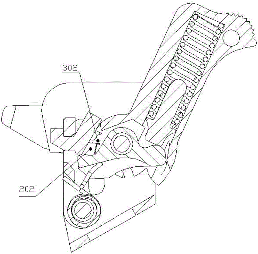
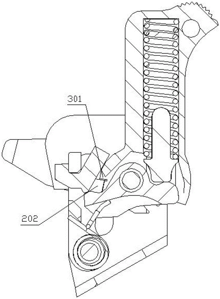
[0055] figure 1 When the manual insurance 1 is in the post-shooting position, the safety tooth 301 on the hammer is stuck on the iron blocking tooth 202 on the iron block, and the hammer 3 is in the firing position at this time. The upper end of the hammer spring 4 is pressed against the bottom of the hammer spring mounting hole 305 of the hammer, and the lower end is in contact with the disc 501 on the hammer spring rod. The ball crown 502 on the hammer spring rod rests on the hammer spring seat. On the spherical surface 602, the safety limit tooth 601 on the hammer spring seat is stuck to the safety positioning groove 103 on the manual safety. At this time, if the operator manually applies a clockwise force to the hammer 3, the hammer 3 will move forward. Rotating clockwise, the barrier iron 2 tends to rotate clockwise under the action of the barrier spring 8. The linkage teeth 302 and single-acting teeth 303 on the hammer squeeze the barrier iron 2 in turn; when the hammer 3 rotates to the hammer When the linkage teeth 302 of the hammer are higher than the iron teeth 202 on the barrier iron and the single-acting teeth 303 on the hammer are lower than the iron teeth 202 on the barrier iron, the operator cancels the clockwise force acting on the hammer 3, The hammer linkage tooth 302 on the hammer will jam the iron blocking tooth 202 on the blocking iron, and the hammer 3 is in the linkage ready-to-fire position at this time. When the hammer 3 rotates until the single-acting tooth 303 on the hammer is higher than the iron-blocking tooth 202 on the iron block, the operator cancels the clockwise force acting on the hammer 3, and the single-acting tooth 303 on the hammer will The iron blocking tooth 202 on the blocking iron is stuck, and the hammer 3 is in the single-action ready to be fired position at this time. The appeal action realizes that when the manual insurance 1 is in the shooting position, the hammer 3 stays in the firing position, the linkage waiting position, and the single-action waiting position.
[0056] in figure 1 The manual safety 1 in the position shown is turned clockwise to figure 2 , Figure 3a , Figure 3b In the position shown, the safety limit tooth 601 on the hammer spring seat is stuck on the inclined surface 105 behind the safety positioning slot 103 on the manual safety, and the anti-iron safety tooth 101 on the manual safety is stuck to the anti-iron limit on the anti-iron Teeth 201, the iron-barrier teeth 202 on the barrier iron block the safety teeth 301 on the hammer when the hammer is in the firing position; the iron-barrier teeth 202 on the barrier iron block the linkage teeth 302 of the hammer when the hammer is in linkage The position to be fired; when the iron stop tooth 202 on the stop iron jams the single-acting tooth 303 of the stuck hammer, the hammer is in the single-acting position to be fired; the hammer 3 is subjected to a single rightward action due to falling, scratching, etc. After the force is applied, the barrier iron 2 cannot be squeezed open, and the hammer 3 cannot be rotated clockwise; the barrier iron 2 alone cannot be squeezed open by the leftward force of the barrier iron safety teeth 101 on the manual insurance, and the barrier iron 2 cannot be rotated counterclockwise. At the same time, the barrier 2 also restricts the counterclockwise rotation of the hammer 3. The appeal action realizes the three-state safety function of the hammer 3 in the firing position, the linkage to be fired position, and the single action to be fired position.
[0057] Such as Figure 4 , 5 , 6 shows that when the single-acting tooth 303 on the hammer is stuck on the iron-barrier tooth 202 on the iron-barrier, the hammer spring 4 is in the maximum compression state. If the operator briefly applies a clockwise direction to the manual insurance 1 The function of the iron stopper limit tooth 201 is squeezed open by the hammer release tooth 102 on the manual insurance to make the iron stopper 2 rotate counterclockwise, the iron stopper tooth 202 on the iron stopper and the single-acting tooth 303 on the hammer Separate, the hammer 3 will rotate counterclockwise under the force of the hammer spring. After rotating a certain angle, the safety release tooth 304 on the hammer contacts the hammer limiting tooth 104 on the manual insurance, and the hammer 3 drives the manual insurance 1. Rotate clockwise, the blocking iron 2 rotates clockwise under the action of the blocking iron spring 8. When the hammer 3, the safety 1, and the blocking iron 2 rotate to Image 6 In the position shown, the safety release tooth 304 on the hammer 3 is separated from the hammer limit tooth 104 on the manual fuse 1, and the fuse limit tooth 601 on the hammer spring seat 6 is gradually jammed into the fuse positioning slot 103 for manual fuse Positioning makes the manual safety 1 rotate to the shooting position, and the linkage tooth 302 on the hammer is stuck on the iron blocking tooth 202 on the blocking iron 2. The above action can be used to rotate the manual insurance 1 to safely release the hammer 3 when there is a bullet in the breech of the pistol and the hammer 3 is ready to be fired to realize the function of releasing the hammer 3 from being fired. During the whole process, the rotation of the hammer 3 is restricted by the hammer limiting tooth 104 on the manual insurance, which can ensure the safety of the pistol during the shooting process.

PUM

no PUM

Description & Claims & Application Information

We can also present the details of the Description, Claims and Application information to help users get a comprehensive understanding of the technical details of the patent, such as background art, summary of invention, brief description of drawings, description of embodiments, and other original content. On the other hand, users can also determine the specific scope of protection of the technology through the list of claims; as well as understand the changes in the life cycle of the technology with the presentation of the patent timeline. Login to view more.

Similar technology patents

Traditional Chinese medicine decoction device

ActiveCN105287216AReduces the risk of inconsistent decoction quality or drug mix-upsSave installation spacePharmaceutical product form changeDomestic articlesMedicinal herbsEngineering
Owner:永春县产品质量检验所福建省香产品质量检验中心国家燃香类产品质量监督检验中心福建

Emergency rescue vehicle

PendingCN107653920ARealize collaborative workSave installation spaceMechanical machines/dredgersEndless track vehiclesEngineeringEmergency rescue
Owner:JIANGSU XCMG CONSTR MASCH RES INST LTD

Classification and recommendation of technical efficacy words

  • Use less parts
  • Save installation space

Vertical solid and liquid separation device

Owner:SHENZHEN OILEER HEALTH SCI & TECH

Microscope machine platform structure

InactiveCN103163714AAvoid safety hazardsUse less partsProjectorsDrive motorMicroscope
Owner:CSMC TECH FAB2 CO LTD

Automatic reset temperature controller

InactiveCN101964276ASimple structureUse less partsThermal switch detailsInduction systemSwitch box
Owner:太平洋电子(昆山)有限公司

Air-conditioner internal unit and air conditioner

PendingCN107525154ASave installation spaceCompact installation spaceCondensate preventionLighting and heating apparatusAirflowSpace requirements
Owner:GREE ELECTRIC APPLIANCES INC OF ZHUHAI
Why Eureka
Try Eureka