Mild detonation fuse separation device design verification test method
A flexible detonating cord and separation device technology, applied in the field of spacecraft structure, can solve problems such as insufficiently clear test boundary requirements, insufficiently comprehensive test items, and insufficiently realistic states, and achieve perfect test items, reasonable state of test pieces, and reduced The effect of the difference between heaven and earth
Active Publication Date: 2016-05-11
BEIJING INST OF ASTRONAUTICAL SYST ENG +1
View PDF6 Cites 7 Cited by
- Summary
- Abstract
- Description
- Claims
- Application Information
AI Technical Summary
Problems solved by technology
[0008] The present invention aims at the deficiencies such as the untrue state of the test piece, the insufficient comprehensiveness of the test items, and the insufficient definition of the test boundary requirements in the current design appraisal test, and establishes a more
Method used
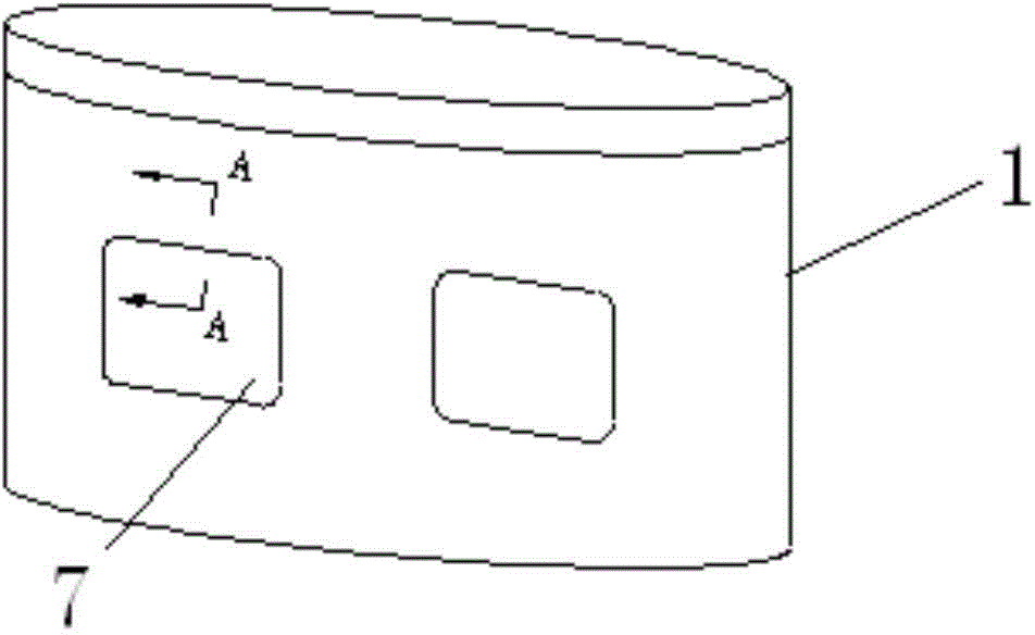
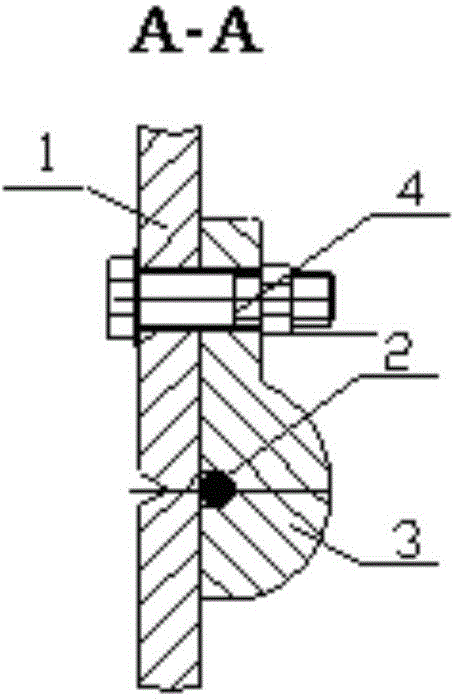
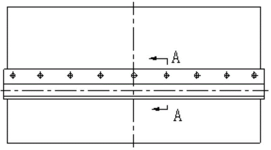
View moreImage
Smart ImageViewing Examples
Examples
 PUM
 Abstract
The invention belongs to the technical field of spacecraft structures, relates to a design verification test method applicable to a mild detonation fuse separation device, and specifically relates to the test piece state, test items, test boundary and the like of a mild detonation fuse separation device. The design verification test method is a reasonable, comprehensive and effective test method for verifying the correctness of design state. According to the method, design verification test of a mild detonation fuse separation device 7 is carried out by combining a 1:1 test piece and a flat-plate test piece. The 1:1 test piece simulates the environmental conditions in the flight process of a spacecraft, the test items include temperature cycle, half-sine shock, sine scanning and random vibration, and high-temperature 1 ignition, low-temperature ignition and room-temperature ignition are carried out after the completion of the tests. The flat-plate test piece simulates the other environmental conditions; test is carried out in multiple branches: (1) 2m drop; (2) high-temperature storage; (3) temperature-humidity-height, vibration and acceleration sequential test; and (4) 12m drop; and high-temperature 2 ignition, low-temperature ignition and room-temperature ignition are carried out in groups after the completion of the first three branch tests.
Description
technical field [0001] The invention belongs to the technical field of spacecraft structures, and relates to a design appraisal test method adapted to a flexible detonating cord separation device, in particular to the state of a test piece, test items, test boundaries, etc. of a flexible detonating cord separation device, and is a reasonable, A comprehensive and effective test method for verifying the correctness of the design state. Background technique [0002] The flexible detonation cord separation device uses flexible detonation cord (MDF: Mild Detonation Fuse) as the separation energy, and cuts and separates the shell of the spacecraft structure through the action of detonation pressure and high-temperature and high-pressure gas. The flexible detonating cord separation device is used in the lateral separation of the American Polaris A3, Minuteman, Poseidon, and Trident missile hoods, etc. This type of separation device is also used in the stage separation and flame exh...
Claims
Login to View More Application Information
Patent Timeline
 IPC IPC(8): G01D21/02G01M13/00
Inventor 孙璟侯金瑛王帅胡勇曾雅琴卢红立佟文敏
Owner BEIJING INST OF ASTRONAUTICAL SYST ENG
Features
- R&D
- Intellectual Property
- Life Sciences
- Materials
- Tech Scout
- Unparalleled Data Quality
- Higher Quality Content
- 60% Fewer Hallucinations
Learn More Browse by: Latest US Patents, China's latest patents, Technical Efficacy Thesaurus, Application Domain, Technology Topic, Popular Technical Reports.
© 2025 PatSnap. All rights reserved.Legal|Privacy policy|Modern Slavery Act Transparency Statement|Sitemap|About US| Contact US: help@patsnap.com


