Mura phenomenon compensation method

A compensation method and phenomenon technology, applied in the direction of instruments, static indicators, etc., can solve the problems affecting the product quality of LCD display panels and the low brightness of the front viewing angle in the area around the panel, so as to correct the adverse effects and improve the product quality.

Active Publication Date: 2016-05-18
TCL CHINA STAR OPTOELECTRONICS TECH CO LTD
5 Cites 51 Cited by

AI-Extracted Technical Summary

Problems solved by technology

[0005] like Figure 1-2 As shown, since the camera is shooting at the center of the LCD display panel (panel), the camera and the area around the panel form an angle of view, and the panel is made of liquid crystal molecules deflecting and transmitting light. Under different angles of view, the surrounding areas of the panel The brightness of the area is different. In low grayscale, the brightness at the side view angle is higher than that at the front view angle, ...

Abstract

The invention provides a Mura phenomenon compensation method. A brightness correction coefficient formula is utilized for calculating the brightness correction coefficient of each position on an LCD display panel, thereby correcting brightness data of the LDC display panel at different gray scales according to the calculated brightness correction coefficient, wherein the brightness data are acquired through photographing by a camera, and furthermore obtaining the corrected brightness data. Furthermore Mura compensation data are acquired according to the corrected brightness data. Finally Mura compensation is performed on the LCD display panel according to the Mura compensation data. Therefore the Mura phenomenon compensation method has functions of preventing an adverse effect on Mura compensation effect caused by photographing angle of the camera, and improving product quality of the LCD display panel.

Application Domain

Technology Topic

Image

  • Mura phenomenon compensation method
  • Mura phenomenon compensation method
  • Mura phenomenon compensation method

Examples

  • Experimental program(1)

Example Embodiment

[0035] In order to further illustrate the technical means adopted by the present invention and its effects, a detailed description is given below in conjunction with the preferred embodiments of the present invention and the accompanying drawings.
[0036] see Figure 5 , the present invention provides a kind of Mura phenomenon compensation method, comprises the following steps:
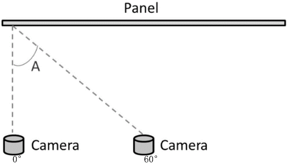
[0037] Step 1. Provide an LCD display panel and a camera, use the camera to take a picture of the LCD display panel displaying a certain grayscale image just above the center point of the LCD display panel, and obtain the brightness of the LCD display panel through the collected image. data.
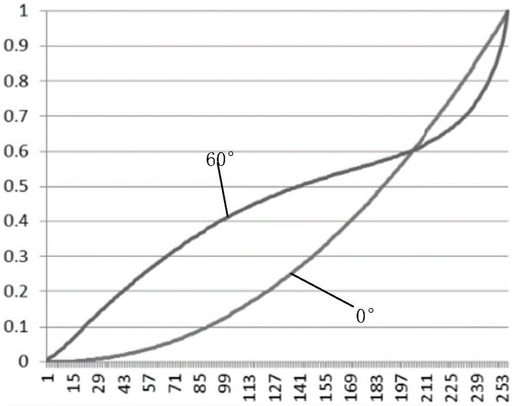
[0038] Specifically, the brightness data of the LCD display panel collected at this time will deviate from the actual display brightness of the LCD display panel due to the different shooting angles of the camera at each position on the LCD display panel. For different display grayscales, the LCD display panel The deviation at the same position is also different. Usually, the brightness data of the LCD display panel collected by the lower grayscale image is greater than the actual display brightness of the LCD display panel. With the continuous improvement of the grayscale, when it reaches a critical value, The collected brightness data of the LCD display panel will be smaller than the real display brightness of the LCD display panel.
[0039] Step 2. Please refer to Image 6 , a rectangular coordinate system is established by taking the center point of the LCD display panel as the coordinate origin, the length and width directions of the LCD display panel are the X axis and the Y axis respectively, and the direction perpendicular to the LCD display panel is the Z axis, combined with the right angle The coordinate system obtains a luminance correction coefficient formula.
[0040] Specifically, the formula of the luminance correction coefficient obtained in the step 2 is the following formula (1):
[0041] Z = 1 - b x 2 + y 2 - - - ( 1 ) ,
[0042] Among them, Z is the brightness correction coefficient, x is the X-axis coordinate value of a certain position on the LCD display panel in the rectangular coordinate system, and y is the Y-axis coordinate of a certain position on the LCD display panel in the rectangular coordinate system value, b is a coefficient related to the grayscale of the picture displayed by the LCD display panel when the camera is shooting;
[0043]In the Cartesian coordinate system, the X-axis and the Y-axis both take half the length of the LCD display panel as a unit, the value range of x is [-1, 1], and the value range of y is [- a, a], a is the ratio of the width to the length of the LCD display panel, and the value range of b is
[0044] Step 3: Using the brightness correction coefficient formula, calculate the brightness correction coefficient of each position on the LCD display panel.
[0045] Step 4: Correct the brightness data according to the calculated brightness correction coefficient to obtain corrected brightness data.
[0046] Specifically, the formula used to correct the brightness data in step 4 is: C1=C2×Z; wherein, C2 is the brightness value of a specific position on the LCD display panel collected in step 1, and Z is the specific position The brightness correction coefficient of , C1 is the brightness value of the specific position after correction.
[0047] Step 5: Obtain Mura compensation data according to the corrected luminance data.
[0048] Specifically, the formula for calculating the Mura compensation data in the step 5 is: M=(C1-d)/e;
[0049] Wherein, M is the Mura compensation data of the specific position, d is the normal brightness of the LCD display panel, and e is the conversion coefficient between the brightness and grayscale of the LCD display panel.
[0050] The normal brightness of the LCD display panel is the brightness of the center point of the LCD display panel collected in step 1.
[0051] Specifically, in the calculation process, an appropriate coefficient b can be selected according to the viewing angle characteristics of the LCD display panel under each grayscale. For example, the grayscale of the picture displayed by the LCD display panel is low. The brightness under the side viewing angle is higher than the brightness under the front viewing angle (that is, the brightness data of the LCD display panel collected at the side viewing angle is greater than the actual display brightness of the LCD display panel), then at this time, the value range of the coefficient b is like Image 6 As shown, since b is greater than or equal to 0, the brightness correction coefficient Z obtained by formula (1) is all less than 1. For example, if b is selected as 0.2, at this time, b is 0.2 and brought into the brightness coefficient compensation formula, and the LCD display can be obtained. The compensation coefficient of the left and right end points of the panel (x=±1, y=0) is 0.8, and then the value c of the collected brightness C2 of the left and right end points of the LCD display panel is multiplied by the compensation coefficient 0.8 to obtain The value of the corrected brightness C1 at the left and right end points of the LCD display panel is 0.8c. Combined with the conversion coefficient e between the brightness and grayscale of the LCD display panel and the normal brightness d of the LCD display panel, the LCD display panel is obtained. The Mura compensation value at the left and right ends of the panel is (0.8*c-d)/e. Since the Mura compensation value is obtained from the corrected brightness C1, the corrected brightness value of 0.8c is higher than the corrected brightness value c It is reduced by 0.2c, thus solving the problem that the gray value of the surrounding area is excessively reduced by the traditional Mura compensation data algorithm, which leads to the low brightness of the surrounding area of ​​the LCD display panel.
[0052] In the same way, when the grayscale of the picture displayed by the LCD display panel is relatively high, under this high grayscale, the brightness of the LCD display panel at the side viewing angle is lower than that at the front viewing angle (that is, the brightness of the LCD display panel collected at the side viewing angle is lower than that of the LCD display panel). The brightness data is less than the actual display brightness of the LCD display panel), the above brightness coefficient formula (1) is also applicable. At this time, the value range of the coefficient b is The obtained brightness compensation coefficient is greater than 1, so as to solve the problem that the traditional Mura compensation data algorithm increases the gray value of the surrounding area excessively, which leads to the high brightness of the surrounding area of ​​the LCD display panel.
[0053] Step 6. Use the Mura compensation data obtained in Step 5 to perform Mura compensation on the LCD display panel.
[0054] Specifically, in the step 1, the camera can take pictures of the LCD display panel three times, and the grayscales of the images displayed on the LCD display panel are different when the three pictures are taken, which are the first, second, and third grayscales, respectively. Thus the obtained brightness data is three copies, which are the first, second, and third brightness data respectively, and correspond to the first, second, and third grayscale display images respectively; the step 2-step 5, the first, second, and third luminance data are corrected respectively, the first, second, and third corrected luminance data are obtained, respectively, and the first, second, and third Mura compensations are obtained respectively. data; then in step 3, use the first, second, and third Mura compensation data to perform Mura compensation on the LCD display panel under the first, second, and third grayscales respectively; wherein, for The selection of the first, second, and third grayscales, in the three calculation processes respectively performed to correct the first, second, and third luminance data, the value of b in formula (1) includes positive values. Numbers and negative numbers are preferred, that is, the first, second, and third grayscales include high grayscales and low grayscales.
[0055] Specifically, in the step 1, the camera may shoot the LCD display panel for more than three times, and the grayscale of the LCD display panel is different for each shooting, so that the obtained brightness data is more than three copies.
[0056] To sum up, the Mura phenomenon compensation method of the present invention uses the brightness correction coefficient formula to calculate the brightness correction coefficient of each position on the LCD display panel. The brightness data of the panel under different grayscales are corrected to obtain corrected brightness data, and then Mura compensation data is obtained according to the corrected brightness data. Finally, Mura compensation is performed on the LCD display panel using the Mura compensation data, thereby correcting The influence of the Mura compensation effect due to the camera's shooting angle has improved the product quality of the LCD display panel.
[0057] As mentioned above, for those of ordinary skill in the art, various other corresponding changes and deformations can be made according to the technical solutions and technical ideas of the present invention, and all these changes and deformations should belong to the protection scope of the claims of the present invention .

PUM

no PUM

Description & Claims & Application Information

We can also present the details of the Description, Claims and Application information to help users get a comprehensive understanding of the technical details of the patent, such as background art, summary of invention, brief description of drawings, description of embodiments, and other original content. On the other hand, users can also determine the specific scope of protection of the technology through the list of claims; as well as understand the changes in the life cycle of the technology with the presentation of the patent timeline. Login to view more.

Similar technology patents

Hydro-desulphurizing combined method

ActiveCN101412928AImprove product qualityIdeal comprehensive processing effectTreatment with hydrotreatment processesWaxChemistry
Owner:CHINA PETROLEUM & CHEM CORP +1

Classification and recommendation of technical efficacy words

Why Eureka
Try Eureka