Automatic soldering machine

a soldering machine and soldering technology, applied in the direction of soldering apparatus, conductors, auxiliaries, etc., can solve the problems of non-uniform solder amount, low productivity, and long fabrication time, and achieve stable production quality and high production efficiency

Inactive Publication Date: 2011-09-06
CHENG UEI PRECISION IND CO LTD
View PDF28 Cites 80 Cited by
  • Summary
  • Abstract
  • Description
  • Claims
  • Application Information

AI Technical Summary

Benefits of technology

[0008]As aforementioned, the insulation removing mechanism of the automatic soldering machine cuts the core wires and strips the insulations at the tops of the core wires without manual cutting and manual stripping of prior art. The soldering mechanism solders the core wires and the soldering portions of the electronic components without manual soldering of prior art. Therefore, a high production efficacy and a stable production quality for soldering process can be realized.

Problems solved by technology

First, the oxidized tops of the core wires have to be manually cut and the insulations of the tops of the core wires also have to be manually stripped to expose the core wires for soldering.
The fabrication time takes too long and the productivity is low.
Besides, the manual operations involve many human factors and the problems of non-uniform solder amounts can easily happen.
Therefore, production quality becomes not stable.

Method used


Image

  • Automatic soldering machine
  • Automatic soldering machine
  • Automatic soldering machine

Examples


Embodiment Construction

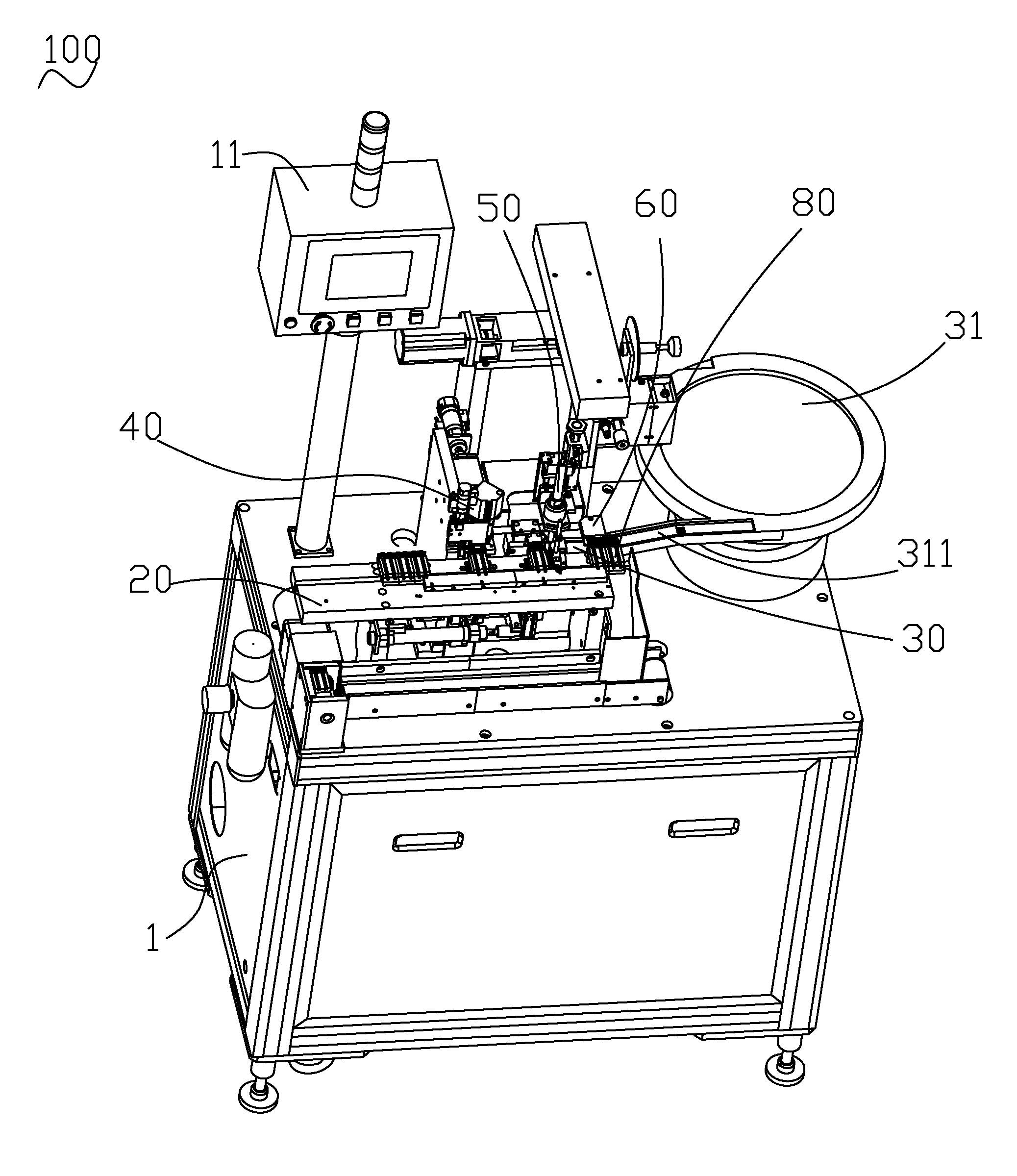
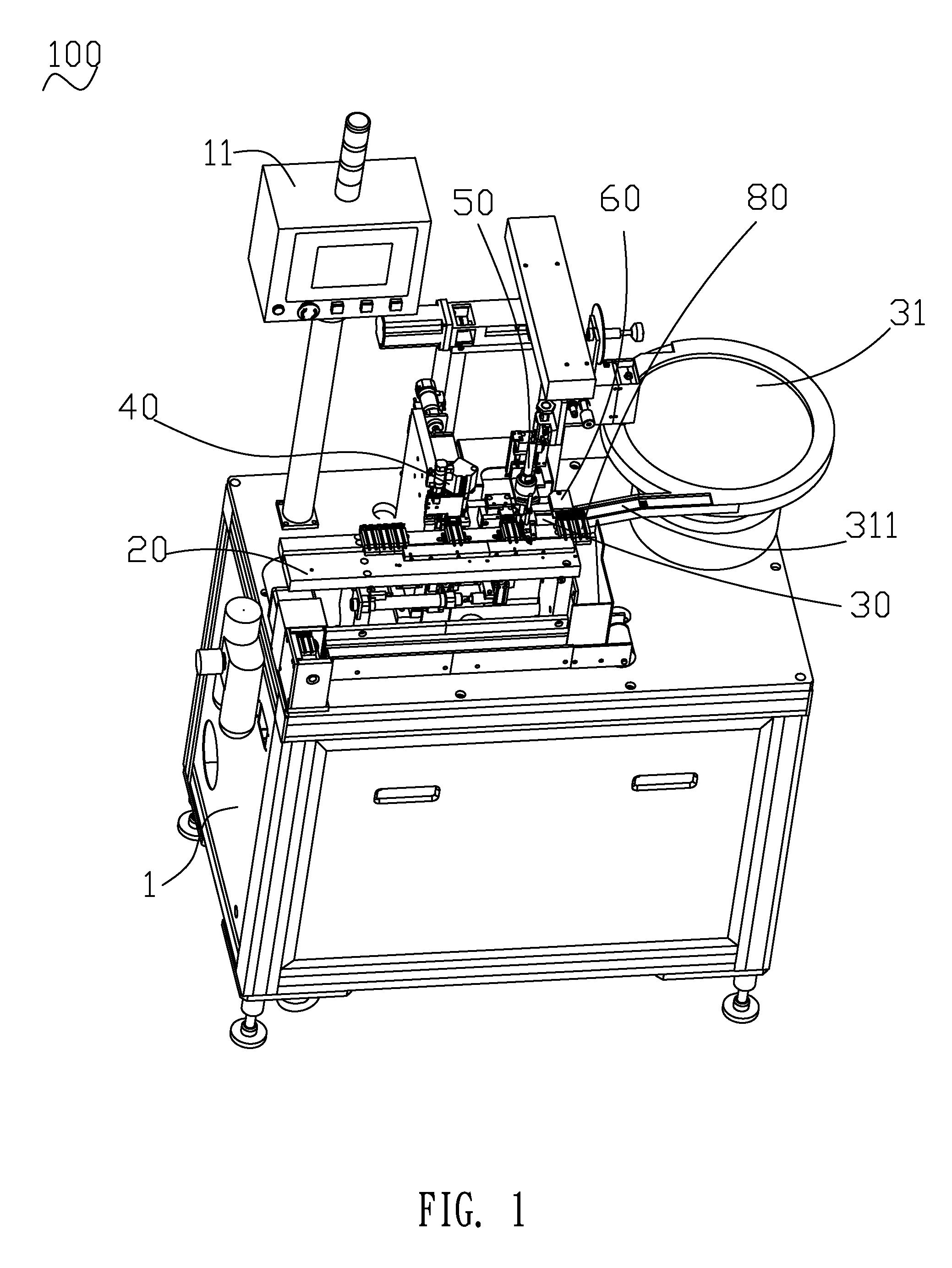
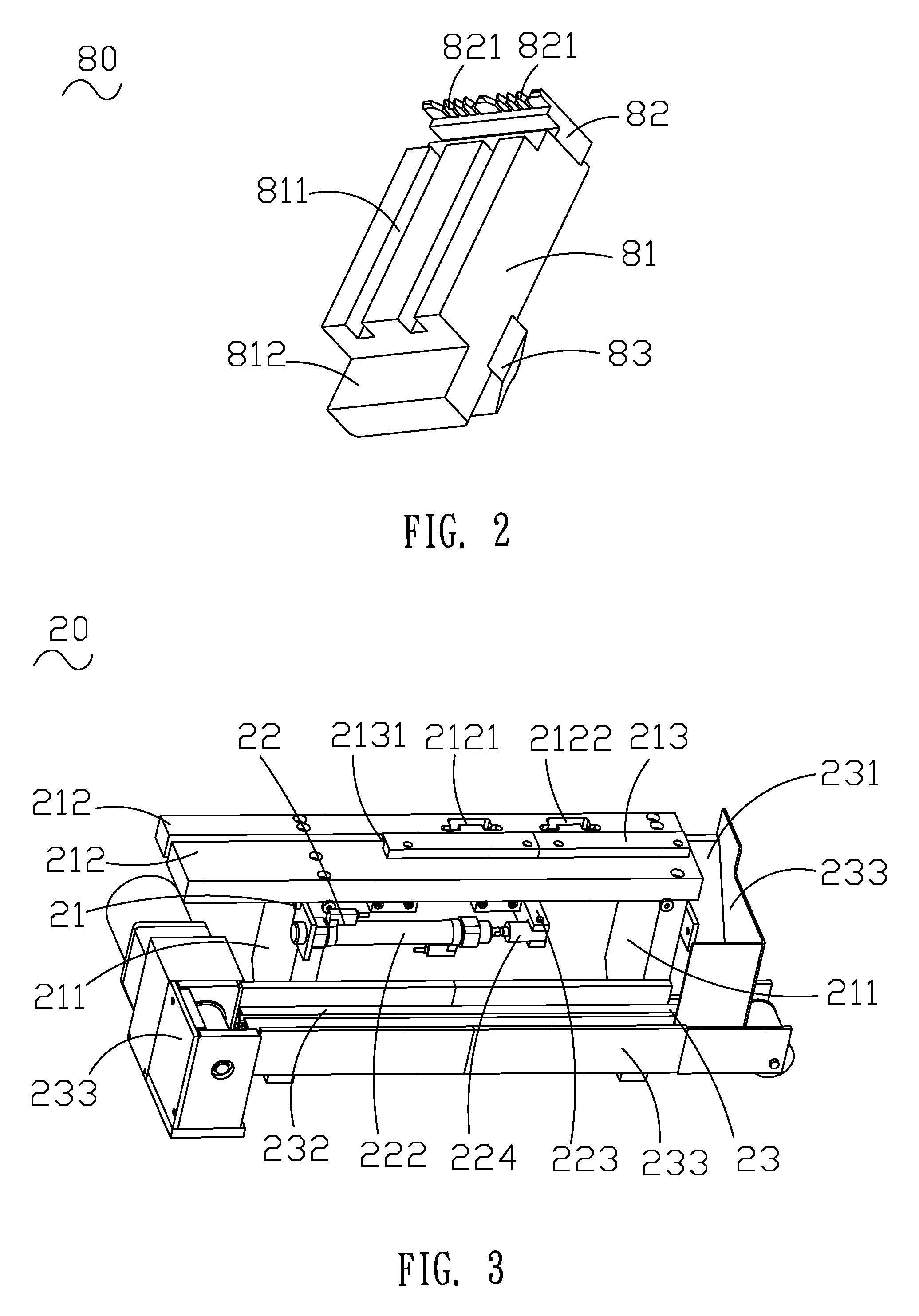
[0019]Please refer to FIG. 1 and FIG. 10. An automatic soldering machine 100 of the present invention is employed for soldering wires (not shown) and electronic components (not shown). Each wire exposes at least one core wire (not shown). Each electronic component has at least one soldering portion (not shown). The automatic soldering machine 100 comprises an equipment 1, a control system, a delivery mechanism 20 and a feeding mechanism 30. The control system is employed to control working procedures, electrical signals and settings of parameters of the automatic soldering machine 100. The control system comprises a host (not shown), an operation interface 11 connected with the host and a plurality of fiber sensors (not shown). Behind the delivery mechanism 20 on the equipment 1, an insulation removing mechanism 40, a soldering mechanism 50 and an unloading mechanism 60 are installed. Under the delivery mechanism 20 on the equipment 1, a locating mechanism 70 is positioned correspon...


PUM

PropertyMeasurementUnit
conductiveaaaaaaaaaa
structure diagramaaaaaaaaaa
timeaaaaaaaaaa

Abstract

An automatic soldering machine for soldering wires, each exposing at least one core wire and electronic components with at least one soldering portion respectively is disclosed. The automatic soldering machine comprises an equipment, a delivery mechanism, a plurality of clamps, a feeding mechanism, an insulation removing mechanism, a soldering mechanism, an unloading mechanism and a programmable control system. The delivery mechanism delivers the wires. The clamps locate the wires. The feeding mechanism conveys the electronic components. The insulation removing mechanism cuts the core wires and strips insulations at tops of the core wires. The soldering mechanism solders the core wires and the soldering portions of the electronic components. The unloading mechanism separates the soldered electronic components and core wires off from the clamps. The programmable control system is connect to the aforesaid mechanisms and controls thereof with high production efficacy and stable production quality.

Description

BACKGROUND OF THE INVENTION[0001]1. Field of the Invention[0002]The present invention generally relates to an automatic soldering machine, and more particularly to an automatic soldering machine for soldering wires and electronic components.[0003]2. Description of Prior Art[0004]When the USB connection cables, the HDMI connection cables and etc. for connecting the electrical devices are fabricated, the wires and the soldering portions of the conductive terminals of the electronic components in the electrical devices have to be soldered. According to prior arts, mainly, a soldering process for the connection cables is a manual soldering. First, the oxidized tops of the core wires have to be manually cut and the insulations of the tops of the core wires also have to be manually stripped to expose the core wires for soldering. Then, an operation of a soldering gun for soldering the exposed core wires with the soldering portions of the conductive terminals of the electronic components h...

Claims


Application Information

Patent Timeline
Patent Type & Authority Patents(United States)
IPC IPC(8): B23K37/04
CPCB23K1/0016B23K3/063B23K2201/38B23K2101/38
Inventor ZHANG, SHAO-BOCHEN, SUNG-LINWU, XIAO-LIN
Owner CHENG UEI PRECISION IND CO LTD
Why Eureka
Try Eureka