A gis-based method for locating fault points of communication optical cables
A technology of communication optical cable and positioning method, which is applied in the direction of electromagnetic wave transmission system, electrical components, transmission system, etc., can solve the problem of inaccurate positioning of fault point coordinates, shorten the time of fault inquiry and troubleshooting, reduce the impact, reduce and prevent the fault of optical cable glitch effect
- Summary
- Abstract
- Description
- Claims
- Application Information
AI Technical Summary
Problems solved by technology
Method used
Image
Examples
Embodiment 1
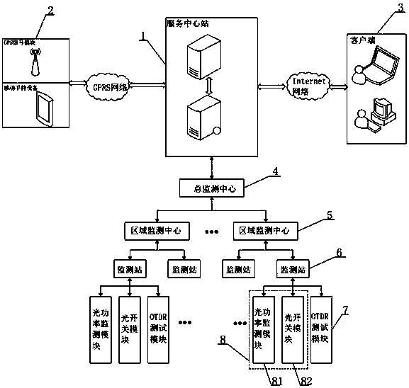
[0045] Such as figure 1 As shown, the present invention includes a monitoring system and a remote monitoring system. The monitoring system includes a mobile terminal 2, a service center station 1 and a client 3. The mobile terminal 2 includes a mobile handheld device and a GPS signal module. The mobile handheld device adopts a smart phone, and the mobile handheld Both the equipment and the GPS signal module exchange data with the service center station 1 through the GPRS network; the service center station 1 includes a central server and a remote GIS server, and the central server accesses the remote GIS server through the Internet network, and can access the electronic map information in the GIS server, The client 3 establishes a connection with the service central station 1 through the Internet network, and can access the optical cable operation information and fault information stored in the central server.
[0046] The remote monitoring system includes a general monitoring...
Embodiment 2
[0066] Such as Figure 4 As shown, the difference between this embodiment and Embodiment 1 is that the remote optical fiber monitoring device also includes an alarm unit 9, the input end of the alarm unit 9 is electrically connected to the monitoring station 6, and the alarm unit 9 adopts a rotary sound and light alarm , when the monitoring unit 8 detects that there is an abnormality in the operating state of the optical fiber core, the monitoring station 6 controls the rotary sound and light alarm to send out a sound and light alarm, so as to warn the operator.
Embodiment 3
[0068] Such as Figure 5 As shown, the difference between this embodiment and Embodiment 2 is that the monitoring unit 8 of the remote optical fiber monitoring device includes two parts: an AIU optical path acquisition unit 83 and an OSU optical path switching unit 84, and the AIU optical path acquisition unit 83 includes a splitter and the optical power monitor, the output end of the splitter is electrically connected to the input end of the optical power monitor; the OSU optical path switching unit 84 includes an optical path one-pole switching module and an optical path two-pole switching module, an optical path one-pole switching module and an optical path two-pole switching module The output ends of the modules are all electrically connected to the monitoring station 6 .
PUM
 Abstract
Description
Claims
Application Information
 - R&D
- Intellectual Property
- Life Sciences
- Materials
- Tech Scout
- Unparalleled Data Quality
- Higher Quality Content
- 60% Fewer Hallucinations
Browse by: Latest US Patents, China's latest patents, Technical Efficacy Thesaurus, Application Domain, Technology Topic, Popular Technical Reports.
© 2025 PatSnap. All rights reserved.Legal|Privacy policy|Modern Slavery Act Transparency Statement|Sitemap|About US| Contact US: help@patsnap.com


