GIS-based communication optical cable online monitoring system and GIS-based communication optical cable fault point positioning method

A communication optical cable and monitoring system technology, which is applied in the field of GIS-based communication optical cable online monitoring system and its fault point location, can solve the problem of inaccurate positioning of fault point coordinates, etc., shorten the time for fault query and troubleshooting, accurately locate, reduce and the effect of preventing fiber optic cable failure

Active Publication Date: 2016-05-18
NANYANG POWER SUPPLY COMPANY OF STATE GRID HENAN ELECTRIC POWER
View PDF8 Cites 19 Cited by
  • Summary
  • Abstract
  • Description
  • Claims
  • Application Information

AI Technical Summary

Problems solved by technology

[0005] In view of this, the purpose of the present invention is to address the deficiencies in the prior art, to provide a GIS-based communication optical cable online monitoring system and its fault point location method, which solves the problem that the fault point coordinates of the existing monitoring system are not accurate enough

Method used


Image

  • GIS-based communication optical cable online monitoring system and GIS-based communication optical cable fault point positioning method
  • GIS-based communication optical cable online monitoring system and GIS-based communication optical cable fault point positioning method
  • GIS-based communication optical cable online monitoring system and GIS-based communication optical cable fault point positioning method

Examples


Embodiment 1

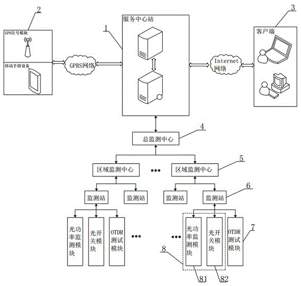
[0046] Such as figure 1 As shown, the present invention includes a monitoring system and a remote monitoring system. The monitoring system includes a mobile terminal 2, a service center station 1 and a client 3. The mobile terminal 2 includes a mobile handheld device and a GPS signal module. The mobile handheld device adopts a smart phone, and the mobile handheld Both the equipment and the GPS signal module exchange data with the service center station 1 through the GPRS network; the service center station 1 includes a central server and a remote GIS server, and the central server accesses the remote GIS server through the Internet network, and can access the electronic map information in the GIS server, The client 3 establishes a connection with the service central station 1 through the Internet network, and can access the optical cable operation information and fault information stored in the central server.

[0047] The remote monitoring system includes a general monitoring...

Embodiment 2

[0068] Such as Figure 4 As shown, the difference between this embodiment and Embodiment 1 is that the remote optical fiber monitoring device also includes an alarm unit 9, the input end of the alarm unit 9 is electrically connected to the monitoring station 6, and the alarm unit 9 adopts a rotary sound and light alarm , when the monitoring unit 8 detects that there is an abnormality in the operating state of the optical fiber core, the monitoring station 6 controls the rotary sound and light alarm to send out a sound and light alarm, so as to warn the operator.

Embodiment 3

[0070] Such as Figure 5 As shown, the difference between this embodiment and Embodiment 2 is that the monitoring unit 8 of the remote optical fiber monitoring device includes two parts: an AIU optical path acquisition unit 83 and an OSU optical path switching unit 84, and the AIU optical path acquisition unit 83 includes a splitter and the optical power monitor, the output end of the splitter is electrically connected to the input end of the optical power monitor; the OSU optical path switching unit 84 includes an optical path one-pole switching module and an optical path two-pole switching module, an optical path one-pole switching module and an optical path two-pole switching module The output ends of the modules are all electrically connected to the monitoring station 6 .


PUM


Abstract

The invention discloses a GIS-based communication optical cable online monitoring system and a GIS-based communication optical cable fault point positioning method. The GIS-based communication optical cable online monitoring system comprises a monitoring system and a remote monitoring system. The GIS-based communication optical cable online monitoring system has functions of remotely monitoring the whole optical cable line in an online manner, monitoring characteristic change and change trend of the optical cable in real time, performing in-time monitoring when a fault is found, effectively reducing and preventing optical cable faults, determining the coordinate of the fault point of the optical cable in a relatively simple manner, shortening fault querying and elimination time, reducing workload of maintenance personnel and improving working efficiency. According to the GIS-based communication optical cable fault point positioning method, a plurality of calculating algorithms for selection are provided according to different actual conditions; different calculating algorithms are performed on different conditions; effect of the outer environment to the system can be maximally reduced; and the fault point can be positioned more accurately.

Description

technical field [0001] The invention relates to the field of communication optical cable fault point monitoring, in particular to a GIS-based communication optical cable online monitoring system and a fault point location method thereof. Background technique [0002] Generally, communication optical cables are used for long-distance transmission. Whether it is laid overhead or buried, the environment around the line is more complicated, and the optical fiber is more sensitive to environmental influences, such as pollution of optical fiber connectors, damp pigtails, and man-made and natural damage. These will cause the fiber to break, causing the communication line to be interrupted. At the same time, in real production and life, due to frequent natural disasters such as artificial construction, road relocation or natural earthquakes, tsunamis, mudslides, etc., fiber optic cable failures may occur every day, resulting in communication interruptions, seriously affecting the no...

Claims


Application Information

Patent Timeline
Patent Type & Authority Applications(China)
IPC IPC(8): H04B10/077H04L29/08
CPCH04B10/0771H04L67/025
Inventor 周松邢友松钱金辉
Owner NANYANG POWER SUPPLY COMPANY OF STATE GRID HENAN ELECTRIC POWER
Why Eureka
Try Eureka