Test analysis system based on optical cable monitoring station

A test analysis and monitoring station technology, applied in transmission systems, digital transmission systems, electromagnetic wave transmission systems, etc., can solve problems such as direct or indirect economic losses, reduce workload, improve work efficiency, and shorten troubleshooting and troubleshooting. effect of time

Inactive Publication Date: 2019-08-02
北京盟力星科技有限公司
View PDF4 Cites 2 Cited by
  • Summary
  • Abstract
  • Description
  • Claims
  • Application Information

AI Technical Summary

Problems solved by technology

It can be seen that the direct or indirect economic losses caused by the interruption of optical fiber communication lines are very large.

Method used


Image

  • Test analysis system based on optical cable monitoring station
  • Test analysis system based on optical cable monitoring station

Examples


Embodiment Construction

[0023] In order to enable those skilled in the art to better understand the solutions of the present invention, the following will clearly and completely describe the technical solutions in the embodiments of the present invention in conjunction with the drawings in the embodiments of the present invention. Obviously, the described embodiments are only It is an embodiment of a part of the present invention, but not all embodiments. Based on the embodiments of the present invention, all other embodiments obtained by persons of ordinary skill in the art without making creative efforts shall fall within the protection scope of the present invention.

[0024] Each will be described in detail below.

[0025] The terms "first", "second", "third" and "fourth" in the description and claims of the present invention and the drawings are used to distinguish different objects, rather than to describe a specific order . Furthermore, the terms "include" and "have", as well as any variatio...


PUM


Abstract

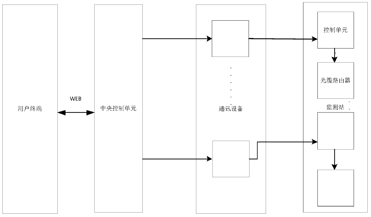
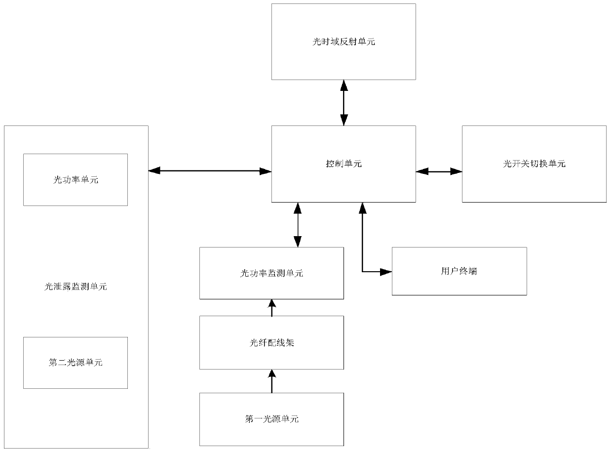
The invention discloses a test analysis system based on an optical cable monitoring station. The system comprises a user terminal, at least one communication device, a central control unit and at least one monitoring station, wherein the user terminal, the communication device and an optical cable resource library unit are respectively connected with the central control unit, and the communicationdevice is connected with the monitoring station. The monitoring station comprises a control unit and a light leakage monitoring unit, and the light leakage monitoring unit is connected with the control unit and is used for directly detecting the optical cable line insertion loss. According to the invention, the whole optical cable line can be monitored remotely and online, the change and the change trend of the optical fiber characteristics are monitored in real time, the optical cable resource information of each monitoring station can be timely mastered and tested and analyzed, the faults can be timely alarmed, optical cable faults can be effectively reduced and prevented, the fault point coordinates of the faults of the optical cables can be determined, the fault query and eliminationtime can be shortened, the workload of maintenance personnel can be reduced, and the work efficiency can be improved.

Description

technical field [0001] The invention relates to the technical field of communication optical cable testing and analysis, in particular to a testing and analyzing system based on an optical cable monitoring station. Background technique [0002] Generally, communication optical cables are used for long-distance transmission. Whether it is laid overhead or buried, the environment around the line is more complicated, and the optical fiber is more sensitive to environmental influences, such as pollution of optical fiber connectors, damp pigtails, and man-made and natural damage. These will cause the fiber to break, causing the communication line to be interrupted. At the same time, in real production and life, due to frequent natural disasters such as artificial construction, road relocation or natural earthquakes, tsunamis, mudslides, etc., fiber optic cable failures may occur every day, resulting in communication interruptions, seriously affecting the normal work of the commun...

Claims


Application Information

Patent Timeline
IPC IPC(8): H04B10/071H04B10/079H04L12/26
CPCH04B10/071H04B10/0791H04B10/0795H04B10/07955H04L43/045
Inventor 涂玉娟帅浔聂帅胡迎东
Owner 北京盟力星科技有限公司
Why Eureka
Try Eureka