filter tower
A technology of filter tower and overload response cylinder, which is applied in the field of filter tower and can solve problems such as easy slippage
- Summary
- Abstract
- Description
- Claims
- Application Information
AI Technical Summary
Problems solved by technology
Method used
Image

Examples
Embodiment 1
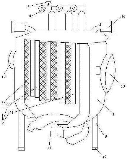
[0027] Embodiment one, see figure 1 , a filter tower, including a filter tower shell 1, a backwash structure 2 and a motor 4. The filter tower housing 1 is provided with a sewage inlet 11, a tap water inlet 12, a water outlet 13, an electric valve 14 and a machine foot 9. The backwash structure 2 is located in the filter tower shell 1 . An anti-slip layer 94 is provided on the lower end surface of the supporting foot 9 . The antiskid layer 94 is made of 20% steel grains and 80% rubber vulcanized together, and the particle size of the steel grains is less than 1 mm. The backwashing structure 2 includes an electric brush 21 , a filter core 22 and a stainless steel filter screen 23 . The electric brush 21 is driven by the motor 4 . The motor 4 is provided with a connection terminal 3 .
[0028] When in use, the power supply is introduced to the motor 4 by connecting the power cord with the terminal 3 together. The present invention is supported by the machine foot 9, and th...
Embodiment 2
[0029] Embodiment two, the difference with embodiment one is:
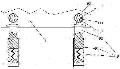
[0030] see figure 2, Machine foot 9 comprises lower section 91 and upper section 92. The anti-slip layer 94 is disposed on the lower end surface of the lower section 91 . The upper end of the lower section 91 is slidably sleeved on the lower end of the upper section 92 . The lower section 81 is provided with a damping spring 93 supporting the upper section 92 . The upper end of the upper section 92 is provided with a connecting ring 921 . An inner ring 922 passes through the connecting ring 921 . The inner ring 922 is connected with the connecting ring 921 through the rubber ring 7 . The inner ring 922 is pierced with connecting pins 923 . The connecting pin 923 is connected with the frame 1 together.
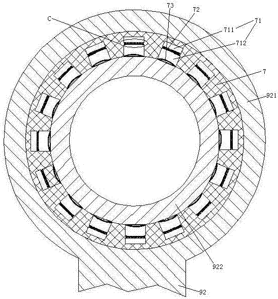
[0031] see image 3 , The inner peripheral surface of the rubber ring 7 is provided with several blind holes 71 distributed along the circumferential direction of the rubber ring (it is also possible for t...
Embodiment 3
[0036] Embodiment three, the difference with embodiment two is:
[0037] see Figure 7 , the connection terminal 3 includes an insulator 33 and a connection copper foil 31 disposed on the surface of the insulator. The insulator 33 is fixedly connected with the casing of the motor 4 . The wiring copper foil 31 is electrically connected with the coil of the motor 53 . The wiring copper foil 31 is provided with a wiring hole 32 . The connection hole 32 penetrates into the insulator 33 . The wiring hole 32 is a blind hole with a closed upper end extending in the vertical direction. The wiring copper foil 31 is located at the lower end of the wiring hole 32 , that is, the opening end. A wiring sleeve 34 is slidably connected to the wiring hole 32 . The wire sleeve 34 includes an insulating segment 341 and a conductive segment 342 . The insulating segment 341 and the conductive segment 342 are distributed axially along the wire sleeve 34 . The insulating segment 341 is locat...
PUM
| Property | Measurement | Unit |
|---|---|---|
| particle size | aaaaa | aaaaa |
Abstract
Description
Claims
Application Information
 - R&D
- Intellectual Property
- Life Sciences
- Materials
- Tech Scout
- Unparalleled Data Quality
- Higher Quality Content
- 60% Fewer Hallucinations
Browse by: Latest US Patents, China's latest patents, Technical Efficacy Thesaurus, Application Domain, Technology Topic, Popular Technical Reports.
© 2025 PatSnap. All rights reserved.Legal|Privacy policy|Modern Slavery Act Transparency Statement|Sitemap|About US| Contact US: help@patsnap.com