Grounding wire winder
A technology of wire winders and ground wires, which is applied in the field of storage devices for ground wires used in power systems, can solve the problems of inconvenient storage and long-distance carrying of ground wire winders, and achieve the effect of simple structure and increased flexibility
- Summary
- Abstract
- Description
- Claims
- Application Information
AI Technical Summary
Problems solved by technology
Method used
Image

Examples
specific Embodiment approach 1
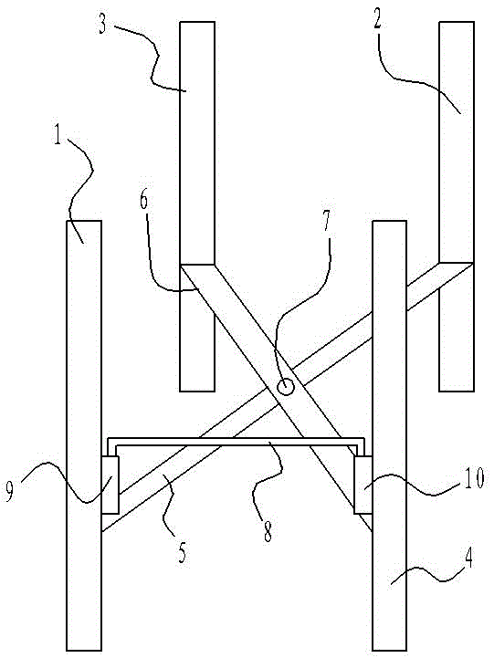
[0028] Such as figure 1 As shown, a grounding wire winder of the present invention includes a support rod set I and a support rod set II, and the support rod set I includes a vertical rod I1, a vertical rod II2 and is used to connect the vertical rod I1 and the The horizontal bar I5 of the vertical bar II2, the support bar group II includes the vertical bar III3, the vertical bar IV4 and the horizontal bar II6 for connecting the vertical bar III3 and the vertical bar IV4, the horizontal bar II6 and the horizontal bar Ⅰ5 is rotatably connected by a rotating shaft 7; a cylinder 9 is provided on the vertical rod Ⅰ1, and a cylinder 10 is provided on the vertical rod Ⅳ4; the ground wire winding device also includes a U-shaped positioning rod 8, and the U-shaped positioning rod The two free ends of 8 are slidingly matched with the cylinder body 9 on the support rod group I and the cylinder body 10 on the support rod group II respectively.
[0029] First adjust the relative position...
specific Embodiment approach
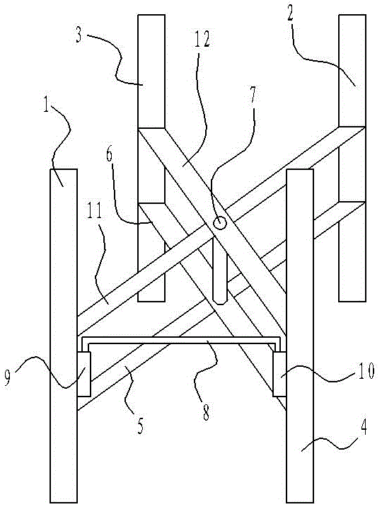
[0031] figure 2 It is another specific embodiment of the present invention. Compared with the specific embodiment 1, the difference between this specific embodiment is that the grounding wire winder according to the present invention, between the vertical rod I1 and the vertical rod II2 There is also a horizontal bar III11, and a horizontal bar IV12 is also provided between the vertical bar III3 and the vertical bar IV4. The horizontal bar III11 and the horizontal bar IV12 are both located above the U-shaped positioning bar 8. The horizontal bar Rod III11 and crossbar IV12 are rotatably connected through said rotating shaft 7 .
[0032] When in use, the difference from Embodiment 1 is that in view of the use of the crossbar III11 and the crossbar IV12, it is convenient to support the wound grounding coil during the winding process of the grounding wire. Therefore, any adjacent two vertical The grounding wires are respectively wound on the pole and the remaining two vertical ...
specific Embodiment approach 3
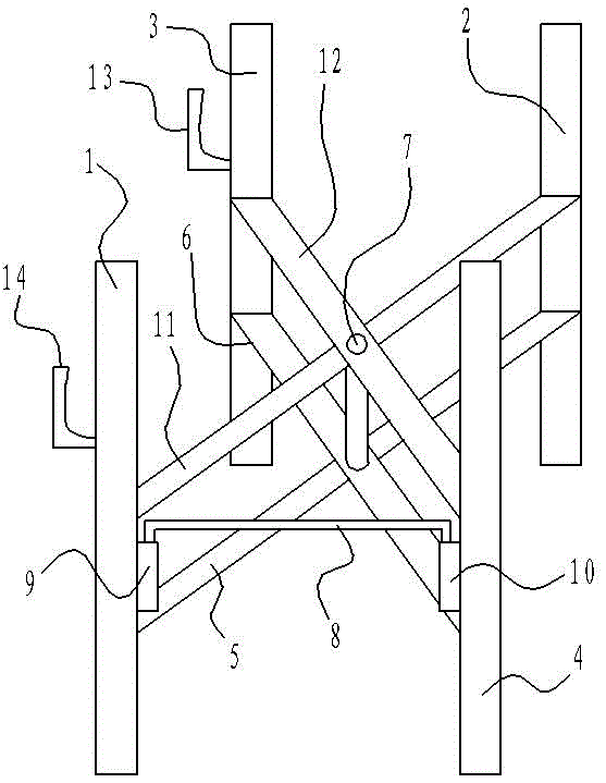
[0033] image 3 It is another specific embodiment of the present invention. Compared with Embodiment 2, this specific embodiment is different in that the present invention is provided with a bobbin frame 14 on the side of the vertical bar I1 of the support rod group I. A winding frame 13 opposite to the winding frame 14 is provided on the side of the vertical bar III3 of the support rod group II, and the winding frame 13 and the winding frame 14 are used in conjunction with each other for use in the winding frame of the present invention. Winding the grounding wire on one side avoids the use of winding the grounding wire from the top of the relevant vertical rod in the above embodiment, and improves the speed of winding the grounding wire to a certain extent, which is more practical.
PUM
 Abstract
Description
Claims
Application Information
 - R&D
- Intellectual Property
- Life Sciences
- Materials
- Tech Scout
- Unparalleled Data Quality
- Higher Quality Content
- 60% Fewer Hallucinations
Browse by: Latest US Patents, China's latest patents, Technical Efficacy Thesaurus, Application Domain, Technology Topic, Popular Technical Reports.
© 2025 PatSnap. All rights reserved.Legal|Privacy policy|Modern Slavery Act Transparency Statement|Sitemap|About US| Contact US: help@patsnap.com