
Eureka
For R&D, Eureka makes reading and utilizing patents & technical documents easy.
Eureka AIR
Designed for self-driven R&D workflows. Generate viable solutions, solve complex R&D challenges, empower your innovation with AI.

Eureka Materials
Designed for material experts only. Revolutionize your material R&D, from search, analyze, to developing new materials.

TechResearch
Generate reliable direction feasibility study reports for your R&D in just a few steps.

TechSeek
Discover and master advanced knowledge NOW. Basics, ideas, possibilities, all at once.

TechMind
As an expert in R&D Theories, TechMind can generates customized viable solutions instantly.

TechRisk
Analyze your overall solution with one click, know your potential R&D risks in advance.

TechMonitor
Get weekly tech updates, stay abreast of the latest tech innovations and key insights.
Batter post bridge
A technology of slanted columns and upright columns, applied in bridges, buildings, etc., can solve the problems of material waste, poor stability, long cycle, etc., and achieve the effect of simple construction process, increased rigidity, and reduced internal force
- Summary
- Abstract
- Description
- Claims
- Application Information
AI Technical Summary
Problems solved by technology
Method used
Image

Examples
Embodiment 1
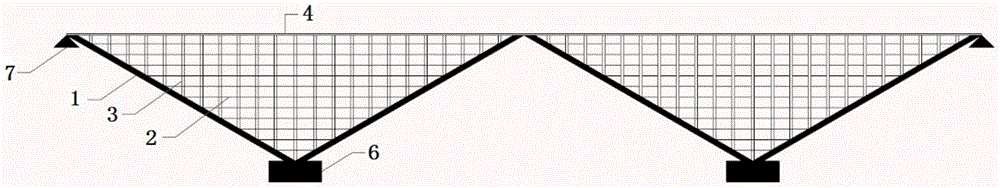
[0022] like figure 1 As shown, a (top-supporting) slanted column bridge includes a bridge deck system 4 and a cap 6; on each cap 6 on both sides of the bridge deck system 4, two longitudinal bridges are vertically symmetrical and have a V-shaped slanted columns 1, and the two slanted columns 1 are connected along the longitudinal direction of the bridge by tie rods 2; the slanted columns 1 are completely below the deck system 4, and columns are set on the slanted columns 1 below the bridge deck system 4 3 supporting the bridge deck system 4; two adjacent slanted columns 1 are consolidated at the ends; the ends of the slanted columns 1 at the front and rear ends of the bridge deck system 4 are directly supported by the support 7. The inclined column 1 adopts a concrete box structure.
[0023] like Figure 4 As shown, the tension S of the tie rod 2 is determined according to the following formula: S=(P+mg) tanα; where, mg is the self-weight of the inclined column segment, P is...
Embodiment 2
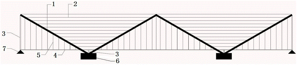
[0025] like figure 2 As shown, a (under-supported) slanted column bridge includes a deck system 4 and a cap 6; on each cap 6 on both sides of the bridge deck system 4, two longitudinal bridges are arranged vertically symmetrically and in the form of V-shaped slanting columns 1, and the two slanting columns 1 are connected along the longitudinal direction of the bridge by tie rods 2; the bridge deck 4 is close to the bottom of the slanting columns 1, and the slanting columns 1 above the bridge deck 4 are provided with suspenders 5 The bridge deck system 4 is supported, and the column 3 is set on the inclined column 1 below the bridge deck system 4 to support the bridge deck system 4; two adjacent inclined columns 1 are consolidated at the ends; the inclined columns at the front and rear ends of the bridge deck system 4 The end of 1 is directly supported by column 3 and support 7. The inclined column 1 adopts a concrete box structure.
[0026] The tension S of the tie rod 2 i...
Embodiment 3
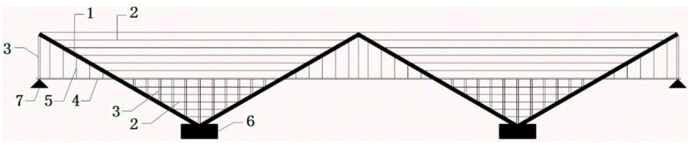
[0028] like image 3 As shown, a (intermediately supported) inclined column bridge includes a bridge deck system 4 and a cap 6; on each cap 6 on both sides of the bridge deck system 4, two longitudinal bridges are arranged vertically symmetrically and in the form of V-shaped slanted columns 1, and the two slanted columns 1 are connected along the longitudinal direction of the bridge by tie rods 2; the bridge deck system 4 is located in the middle of the slanted columns 1, and columns are set on the slanted columns 1 below the bridge deck system 4 3 support the bridge deck system 4, set suspenders 5 on the inclined column 1 above the bridge deck system 4 to support the bridge deck system 4; two adjacent inclined columns 1 are consolidated at the ends; The end of the column 1 is directly supported by the column 3 and the support 7. The inclined column 1 adopts a steel box structure.
[0029] The tension S of the tie rod 2 is determined according to the following formula: S=(P+...
PUM
 Abstract
Description
Claims
Application Information
 - R&D Engineer
- R&D Manager
- IP Professional
- Industry Leading Data Capabilities
- Powerful AI technology
- Patent DNA Extraction
Browse by: Latest US Patents, China's latest patents, Technical Efficacy Thesaurus, Application Domain, Technology Topic, Popular Technical Reports.
© 2024 PatSnap. All rights reserved.Legal|Privacy policy|Modern Slavery Act Transparency Statement|Sitemap|About US| Contact US: help@patsnap.com