Pressure test pit

A pit cover and anti-extrusion technology, used in mechanical equipment, engineering safety devices, etc., can solve problems such as non-compliance with safety production specifications, equipment parts falling off impact force, and equipment loss in test pits, so as to reduce the risk of pressure testing and increase The effect of large rigid strength and saving pressure test time

Inactive Publication Date: 2016-05-25
SICHUAN NAUTILUS IND EQUIP OPERATION MANAGEMENT CO LTD
View PDF5 Cites 4 Cited by
  • Summary
  • Abstract
  • Description
  • Claims
  • Application Information

AI Technical Summary

Problems solved by technology

Existing test pits are usually built in the workshop, and there is no protective device on the upper part. Due to the high pressure inside the equipment, if there is an operation error or the internal pressure exceeds the limit of the equipment itself during the pressure test, equipment parts may appear. Falling off produces a super impact force, which may easily cause loss of equipment outside the test pit and casualties, and does not comply with safety production regulations

Method used


Image

  • Pressure test pit
  • Pressure test pit
  • Pressure test pit

Examples


Embodiment 1

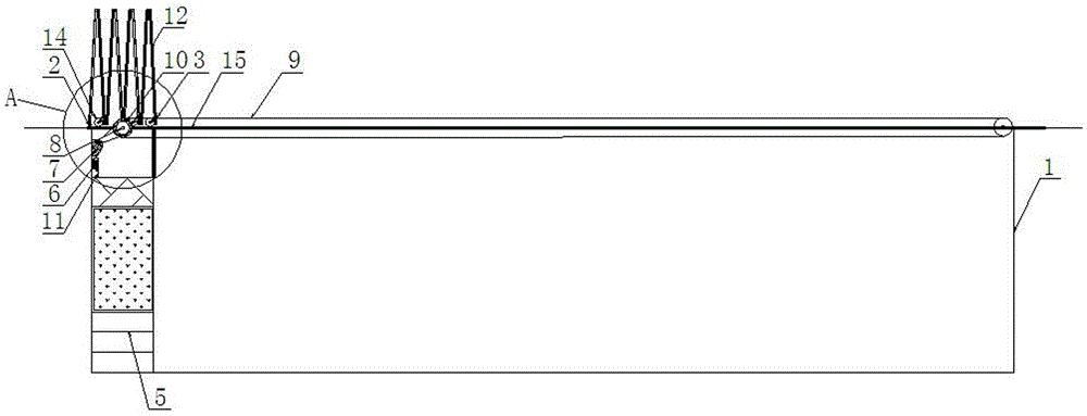
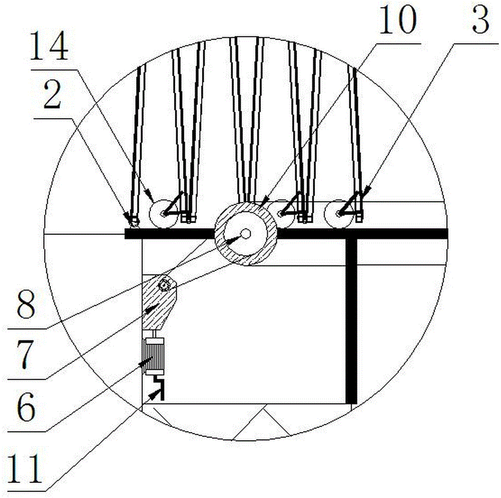
[0038] A pressure test pit, comprising a pit body 1, a foldable pit cover and a pit cover drive mechanism, the foldable pit cover is slidably arranged above the pit body 1, the foldable pit cover includes a positioning end 2 and a driving end 3, The positioning end 2 of the foldable pit cover is movably connected to the end of the pit body 1, and the driving end 3 of the foldable pit cover is movably connected with the pit cover driving mechanism.

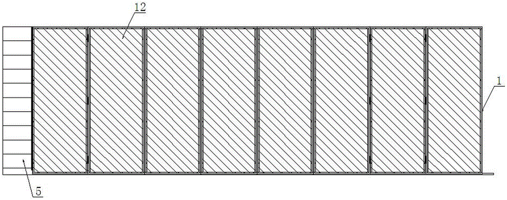
[0039] In this embodiment, the foldable pit cover includes a plurality of cover plates 12 that are movably connected in sequence. Connect them with pins, and fill the frame with cover plates 12 of equal size. The cover plates 12 are Kablon PC endurance boards, and the two adjacent cover plates 12 are connected by hinges.

[0040] In this embodiment, the pit cover driving mechanism includes a motor 6, a reducer 7, two linkage shafts 8 and two chains 9, and the two linkage shafts 8 are respectively rotated and arranged at both ends o...

Embodiment 2

[0045] A pressure test pit, comprising a pit body 1, a foldable pit cover and a pit cover drive mechanism, the foldable pit cover is slidably arranged above the pit body 1, the foldable pit cover includes a positioning end 2 and a driving end 3, The positioning end 2 of the foldable pit cover is movably connected to the end of the pit body 1, and the driving end 3 of the foldable pit cover is movably connected to the pit cover driving mechanism.

[0046] In this embodiment, the foldable pit cover includes a plurality of cover plates 12 that are movably connected in turn, and the cover plates 12 are provided with an anti-extrusion portion 13, and the anti-extrusion portion 13 has the characteristics of cushioning and anti-extrusion. It is made of soft materials, such as rubber, foam, etc., and the anti-extrusion portion 13 is hemispherical, square or circular. The anti-extrusion parts 13 on any two adjacent cover plates 12 on the multiple cover plates 12 are symmetrical, and wh...

Embodiment 3

[0048] A pressure test pit, comprising a pit body 1, a foldable pit cover and a pit cover drive mechanism, the pit body 1 is fixedly provided with a partition wall 16 for dividing the pit body 1 into two pit chambers 4, the foldable There are two sets of pit covers and pit cover drive mechanisms. The two sets of foldable pit covers are respectively slidably arranged above the two pit chambers 4, and the positioning ends 2 of the two sets of foldable pit covers are respectively located at both ends of the pit body 1. The two sets of pit cover driving mechanisms are respectively connected with the driving ends 3 of the two sets of foldable pit covers. Wherein, the two pit chambers 4 are independent of each other, and can be pressure tested at the same time, or one of them can be tested independently, and the foldable pit covers on the two pit chambers 4 are unfolded and folded in opposite directions.

[0049] In this embodiment, the two pit chambers 4 are provided with stairs 5 ...


PUM


Abstract

The invention discloses a pressure test pit. The pit comprises a pit body, a folding-type pit cover and a pit cover driving mechanism, wherein the folding-type pit cover is arranged at the upper part of the pit body in a sliding manner and comprises a positioning end and a driving end; the positioning end of the folding-type pit cover is movably connected to the end part of the pit body; and the driving end of the folding-type pit cover is movably connected with the pit cover driving mechanism. According to the pressure test pit, firstly automatic opening and closing of the pit body can be quickly realized and secondly the pit body can be enabled to be in a relatively sealed state during testing, so that a situation caused by accidental injury is instantly compressed in the pit body and the pressure test risk is lowered.

Description

technical field [0001] The invention relates to the technical field of pressure testing, in particular to a pressure testing pit. Background technique [0002] The pressure test pit is a place for the factory to conduct pressure tests on the equipment that needs to be tested. It is usually a square inner pit, standing below the ground. Existing test pits are usually built in the workshop, and there is no protective device on the upper part. Due to the high pressure inside the equipment, if there is an operation error or the internal pressure exceeds the limit of the equipment itself during the pressure test, equipment parts may appear. If it falls off, it will generate a super strong impact force, which will easily cause the loss of equipment outside the test pit and casualties, and it does not meet the safety production regulations. Contents of the invention [0003] The purpose of the present invention is to solve the above-mentioned problems existing in the prior art, ...

Claims


Application Information

Patent Timeline
Patent Type & Authority Applications(China)
IPC IPC(8): F16P1/00
CPCF16P1/00
Inventor 金松涛邓懿瀛郑晓平
Owner SICHUAN NAUTILUS IND EQUIP OPERATION MANAGEMENT CO LTD
Why Eureka
Try Eureka