Image formation device
An imaging device and an imaging technology, which are applied in the direction of equipment, instruments, optics, etc. of the electrical recording process using charge patterns, can solve the problem that the operating rod 28 cannot rotate at a large angle, etc.
- Summary
- Abstract
- Description
- Claims
- Application Information
AI Technical Summary
Problems solved by technology
Method used
Image

Examples
Embodiment 1
[0020] (imaging equipment)
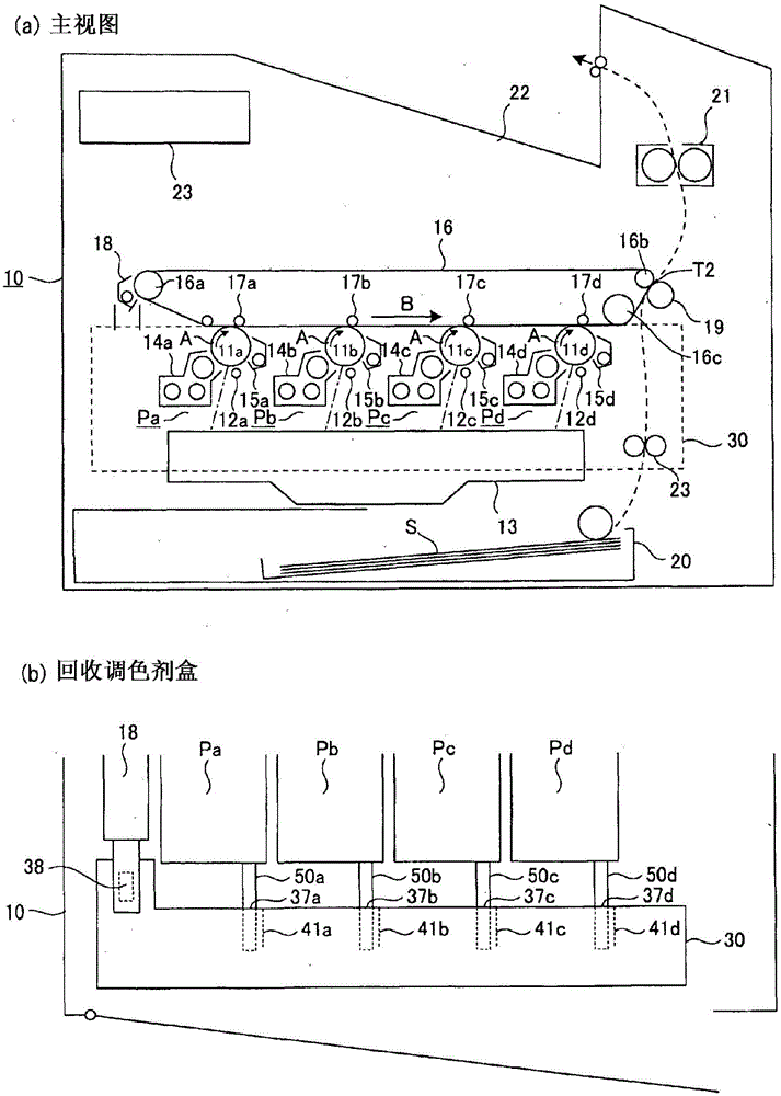
[0021] figure 1 is a view describing the structure of the image forming apparatus in this embodiment. More specifically, figure 1 (a) is a vertical sectional view of the imaging device, figure 1 (b) is a view depicting a state where the collected toner box is attached to the transfer portion of the image forming apparatus.
[0022] refer to figure 1 (a), the image forming apparatus 10 is a so-called tandem type and also a so-called intermediate transfer type full-color printer. The full-color printer has an intermediate transfer belt 16 and image forming portions Pa, Pb, Pc, and Pd aligned along the intermediate transfer belt 16 so as to form yellow, magenta, Cyan and black toner image. The operation of the imaging device 10 is controlled by the control section 23 of the device 10 .
[0023] In the image forming portion Pa, a yellow toner image is formed on its photosensitive drum 11 a and transferred onto the intermediate transfer belt 16 ....
Embodiment 2
[0105] Image 6 is a view showing the low reaction force portion of the rib of the seal baffle 52 . Figure 7 is a view showing the shutter mechanism in the second embodiment of the present invention. Image 6 (a), 6(b) and 6(c) relate to the first, second and third embodiments, respectively. Figure 7 (a) and Figure 7 (b) Respectively about when the shutter is closed and when the shutter is opened. Figure 7 (c) is a view of a shutter driving portion with which the collected toner box 30 is provided.
[0106] refer to Image 6 (a), said Image 6 (a) is a developed front view of the sealing shutter 52, depicting the screw guide of the sealing shutter 52. In the first embodiment, the helix angle α2 of the low reaction force rib 52c is 80 degrees (α2=80).
[0107] refer to Image 6(b), in the second embodiment, the helix angle α2 of the low reaction force rib 52c is 90 degrees (α2=90). The structure of the image forming apparatus 10 in the second embodiment is the same...
Embodiment 3
[0114] The structure of the collected toner box 30 in the third embodiment is the same as that in the first embodiment, except that the low reaction force rib 52c of the seal flap 52 is provided with a protrusion for when the collected toner box 30 clicks as it settles into its designated position in imaging device 10 . Therefore, with the first embodiment in Image 6 The counterparts shown in (a) are structurally identical, in Image 6 Components of the image forming apparatus 10 and collected toner box 30 shown in (c), parts thereof, and the like are given the same reference numerals as those of their counterparts, and will not be described here so as not to repeat the same description .
[0115] refer to Image 6 (c), in the third embodiment, the low reaction force rib 52c is provided with the protruding piece 52f so that when the process of pushing the collected toner box 30 into the image forming apparatus 10 ends, when the collected toner box 30 It makes a clicking s...
PUM
 Abstract
Description
Claims
Application Information
 - Generate Ideas
- Intellectual Property
- Life Sciences
- Materials
- Tech Scout
- Unparalleled Data Quality
- Higher Quality Content
- 60% Fewer Hallucinations
Browse by: Latest US Patents, China's latest patents, Technical Efficacy Thesaurus, Application Domain, Technology Topic, Popular Technical Reports.
© 2025 PatSnap. All rights reserved.Legal|Privacy policy|Modern Slavery Act Transparency Statement|Sitemap|About US| Contact US: help@patsnap.com