Shearing mechanism of electric scissors

A technology of shearing mechanism and electric scissors, which is applied in the field of shearing mechanism, can solve the problems of scrapped blades, small shearing force, and fast blade wear, and achieve the effects of not being easy to roll, high shearing efficiency, and simple structure

Inactive Publication Date: 2016-06-01
NINGBO ZHENHAI MIFENG ENERGY SAVING & ENVIRONMENT PROTECTION TECH
View PDF0 Cites 1 Cited by
  • Summary
  • Abstract
  • Description
  • Claims
  • Application Information

AI Technical Summary

Problems solved by technology

Common electric scissors are mainly electric scissors with two blades hinged to each other. Most of the existing hinged electric scissors are single-blade shears. Soon, it is inconvenient to replace
Moreover, for some round, thin and hard cylindrical materials, when the hinged electric scissors are cutting, if the shearing force is not large enough or the material to be cut is too hard, the cylindrical material is very easy to get stuck on the cutting edge of the blade. Sliding horizontally will cause a lot of wear on the cutting edge of the blade. If the cutting does not exceed a hundred times, the blade of the articulated electric scissors will basically be scrapped, which brings great losses to the user.

Method used


Image

  • Shearing mechanism of electric scissors

Examples


Embodiment Construction

[0010] In order to have a further understanding and understanding of the structural features of the present invention and the achieved effects, the preferred embodiments and accompanying drawings will be used for a detailed description, as follows:

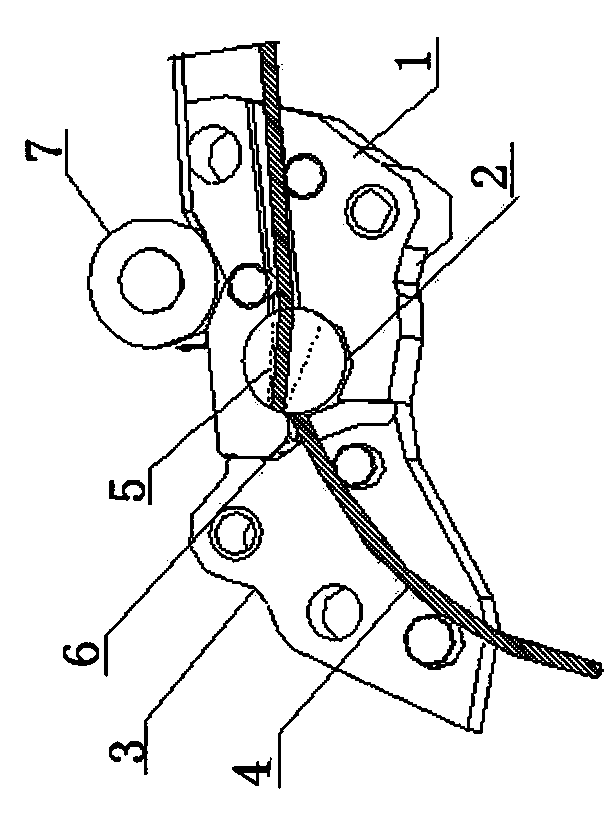
[0011] Such as figure 1 As shown, a shearing mechanism of electric scissors includes a fixed block 1, a shear shaft 2 arranged on one side of the fixed block 1 and movably connected with the fixed block, and a fixed block backing plate 3 arranged at the outlet of the fixed block; Both the fixed block 1 and the backing plate 3 of the fixed block are provided with a placement groove 4, and the shear shaft 2 is provided with a through hole 5 intersecting with the placement groove 4, and one end of the shear shaft 2 is provided with a rotary drive device, and the fixed block 1 One side of one side is provided with a shear opening 6, and when the shear shaft 2 rotates, the shear surface of the fixed block 1 forms a scissor opening with...


PUM


Abstract

The invention relates to a shearing mechanism of electric scissors. The shearing mechanism comprises a fixed block, a shearing shaft arranged on one side of the fixed block and movably connected with the fixed block and a fixed block base plate arranged at an outlet of the fixed block. The fixed block and the fixed block base plate are each provided with a containing groove. The shearing shaft is provided with multiple through holes which communicate with the containing grooves. One end of the shearing shaft is provided with a rotary driving device. One side of the fixed block is provided with a shearing mouth. When the shearing shaft rotates, a scissor mouth is formed by the shearing surface of the fixed block and the edge of the corresponding through hole of the shearing shaft. The through holes in the shearing shaft are located in the circumferential surface of the shearing shaft. The number of the containing grooves in the fixed block and the fixed block base plate corresponds to the number of the through holes in the shearing shaft. The junction of the containing grooves in the fixed block and the fixed block base plate is located at the shearing mouth of the fixed block. When the shearing shaft is rotated, multiple pieces of materials can be sheared. In the shearing process, the cylindrical materials are not likely to roll and are directly cut off by the shearing mouth of the fixed block. The shearing mechanism is simple in structure and high in shearing efficiency.

Description

technical field [0001] The invention relates to a shearing mechanism, in particular to a shearing mechanism of electric scissors. Background technique [0002] Portable electric scissors are mainly used for cutting materials such as thin steel plates, leather, carpets or PVC boards, which can greatly reduce work intensity and improve work efficiency. Common electric scissors are mainly electric scissors with two blades hinged to each other. Most of the existing hinged electric scissors are single-blade shears. Soon, it is inconvenient to replace. Moreover, for some round, thin and hard cylindrical materials, when the hinged electric scissors are cutting, if the shearing force is not large enough or the material to be cut is too hard, the cylindrical material is very easy to get stuck on the cutting edge of the blade. Horizontal sliding will cause great wear and tear on the cutting edge of the blade. If the cutting does not exceed a hundred times, the blade of the articulat...

Claims


Application Information

Patent Timeline
Patent Type & Authority Applications(China)
IPC IPC(8): B21F11/00
Inventor 米钢山
Owner NINGBO ZHENHAI MIFENG ENERGY SAVING & ENVIRONMENT PROTECTION TECH
Why Eureka
Try Eureka