
A centering clamping device

A clamping device and clamping technology, used in workpiece clamping devices, drilling equipment, earth-moving drilling, etc., can solve the problems of small application range, low operation efficiency, difficult clamping, etc., and achieve flexible and convenient adjustment and service life. Long, suitable for a wide range of diameters

Active Publication Date: 2017-08-08
TAIZHONG TIANJIN BINHAI HEAVY MACHINERY
View PDF5 Cites 0 Cited by
  • Summary
  • Abstract
  • Description
  • Claims
  • Application Information

AI Technical Summary

Problems solved by technology

[0004] Based on the above problems, the present invention provides a centering and clamping device to solve the problems of existing equipment such as difficulty in centering and clamping, low operating efficiency, inconvenient operation, and small application range

Method used

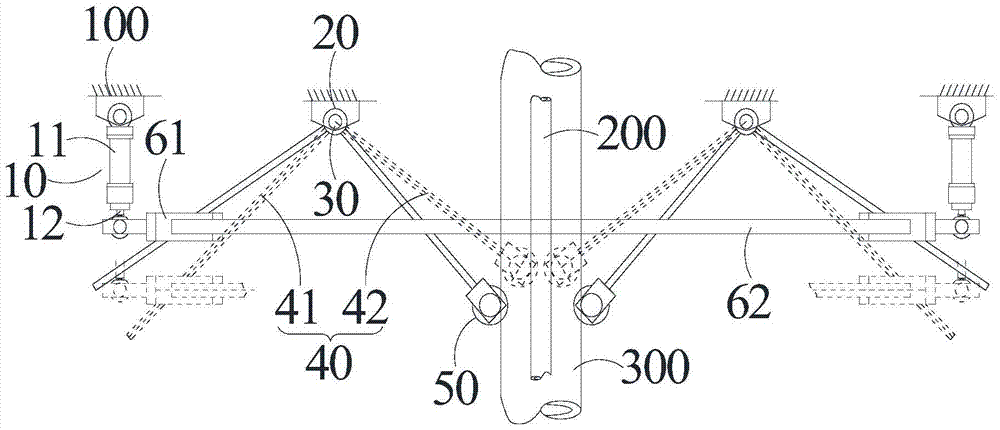
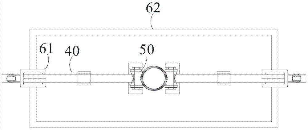

Image

  • A centering clamping device
  • A centering clamping device

Examples


Embodiment Construction

[0009] Example embodiments will now be described more fully with reference to the accompanying drawings. Example embodiments may, however, be embodied in many forms and should not be construed as limited to the embodiments set forth herein; rather, these embodiments are provided so that this disclosure will be thorough and complete, and will fully convey the concept of example embodiments to those skilled in the art. In the drawings, the thicknesses of regions and layers may be exaggerated for clarity. The same reference numerals in the drawings denote the same or similar structures, and thus their detailed descriptions will be omitted.

[0010] Furthermore, the described features, structures, or characteristics may be combined in any suitable manner in one or more embodiments. In the following description, numerous specific details are provided in order to give a thorough understanding of embodiments of the invention. However, one skilled in the art will appreciate that th...


PUM


Abstract

The invention provides a centered clamping device. The centered clamping device comprises at least two transmission mechanisms. Each transmission mechanism comprises a driving cylinder, a driving sleeve, a shaft seat, a shaft, a movable support and a guide wheel. Each movable support comprises a first arm and a second arm, one portion of each first arm is sleeved with the corresponding driving sleeve, and in the motion process, each driving sleeve drives the corresponding first arm to rotate around the corresponding shaft; each guide wheel is connected with the other end of the corresponding second arm and can rotate around the corresponding second arm; a clamped object is located between the guide wheels, and when each piston is located at the first position, the guide wheels are not in contact with the clamped object, and the clamped object is in the non-centered-clamping state; in the process that the pistons stretch out of the position away from a working platform, the pistons drive the driving sleeves to move, and the movable supports are made to rotate around the shafts, and therefore the guide wheels move towards the clamped object; and when the pistons move to the second position, the guide wheels are in contact with the clamped object, the axis of the clamped object and the center axis of the centered clamping device are located on the same straight line, and the clamped object is in the centered clamping state.

Description

technical field [0001] The invention relates to the field of drilling equipment, in particular to a centering and clamping device for a drill pipe or casing. Background technique [0002] During the drilling construction process, it is often necessary to center and clamp the drill pipe and / or casing, and then carry out the operation of connecting the drill pipe and casing. Most of the traditional drilling equipment does not have such a centering and clamping device, and tools such as slips need to be manually operated for centering, which results in low operating efficiency and high labor intensity. [0003] In addition, there are mainly two types of centering devices currently on the market: one uses an elastic centering mechanism, that is, an elastic sheet is used for centering. This centering method is suitable for occasions where there is little difference in pipe diameter. After a long period of use, when used for small pipe diameters, there will be problems of insuffi...

Claims


Application Information

Patent Timeline
Patent Type & Authority Patents(China)
IPC IPC(8): B25B11/00E21B19/24
CPCB25B11/00E21B19/24
Inventor 孙福邱成国贾涛丁全智王旭辉王秉权
Owner TAIZHONG TIANJIN BINHAI HEAVY MACHINERY
Learn More