
Multifunctional self-locking wrench

A multi-functional, self-locking technology, used in wrenches, pliers, manufacturing tools, etc., can solve problems such as damage to the shape of the nut, large damage to the screwed object, and inability to screw the nut of a tubular object.

Active Publication Date: 2016-06-01
临沂高新自来水有限公司
View PDF7 Cites 3 Cited by
  • Summary
  • Abstract
  • Description
  • Claims
  • Application Information

AI Technical Summary

Problems solved by technology

[0002] Traditional wrenches can only screw hex nuts and square nuts, but cannot screw tubular objects and nuts of other shapes
When the nut is rusted, due to the insufficient force of the wrench, the nut cannot be unscrewed and may slip off, and the shape of the nut will also be damaged
Moreover, after the traditional wrench has finished screwing the nut once, the reset operation is difficult. It is often necessary to take out the wrench from the nut, and then return to the nut to lock the nut, and repeat the operation of screwing the nut
In addition, when screwing objects with traditional wrenches, it is necessary to repeatedly adjust the worm gear to find the opening distance of the wrench, and the wrench is also very easy to loosen during repeated clamping, which brings great difficulty to the operation.
The pipe wrench is mainly used for twisting tubular objects. Because the pipe wrench is heavy and has teeth on both sides, it will cause great damage to the wrung object, so the scope of use of the pipe wrench is limited.

Method used


Image

  • Multifunctional self-locking wrench
  • Multifunctional self-locking wrench
  • Multifunctional self-locking wrench

Examples


Embodiment Construction

[0021] Below in conjunction with accompanying drawing, by describing embodiment, the present invention will be further described:

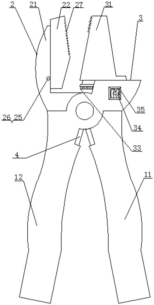
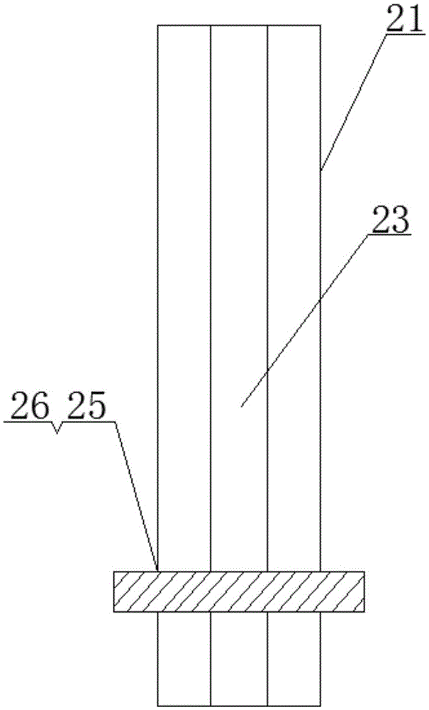
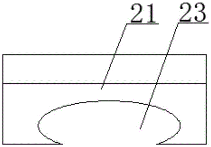
[0022] Such as Figures 1 to 4 As shown, a multifunctional self-locking wrench of the present invention includes a handle, and the handle includes two first handles 11 and second handles 12 that are mutually rotatably connected. The tops of the first and second handles 11 and 12 are respectively provided with first, Two clamping parts 2, 3, the first clamping part 2 is located above the second handle 12, the second clamping part 3 is located above the first handle 11, and the first clamping part 2 includes a vertical fixed claw 21 and The slider I22 on the fixed claw 21 is provided with an elliptical chute I23 along the vertical direction on the side of the fixed claw 21 facing inward, and the top and bottom of the slider I22 are provided to slide in the chute I23 The blocking block 24, the sliding block I22 and the fixed claw 21 are slidably con...


PUM


Abstract

The invention discloses a multifunctional self-locking wrench. The multifunctional self-locking wrench comprises handles, wherein the handles comprise a first handle and a second handle, a first clamping part and a second clamping part are arranged at the top of the first handle and the top of the second handle respectively, a sliding block I is arranged at the first clamping part and is matched with a sliding groove I, a through hole is formed in the position, close to the bottom, of the first clamping part, a stop bolt is mounted in the through hole, and obliquely downward sawteeth I are arranged at the upper half of the sliding block I; the second clamping part comprises a movable claw and a sliding groove II which are glidingly connected with each other; when a nut or a tubular object is tightened, the obliquely downward sawteeth are arranged at the upper half of the sliding block I of the first clamping part, the stop bolt is matched with a stop block, the sliding block I is limited, the sawteeth are matched with the movable claw of the second clamping part, the nut or the tubular object is locked, and skidding is prevented, so that the nut or the tubular object can be tightened quickly and easily by the aid of the multifunctional self-locking wrench. Besides, the multifunctional self-locking wrench can also be used as a monkey wrench, an object is placed between the lower half of the sliding block I and the movable claw to be clamped, and the object is prevented from being damaged.

Description

technical field [0001] The invention relates to an auxiliary tool, in particular to a multifunctional self-locking wrench. Background technique [0002] Traditional wrenches can only twist hexagonal nuts and square nuts, but cannot twist tubular objects and nuts of other shapes. When the nut is rusted, due to the insufficient force of the wrench, the nut cannot be unscrewed, and there is a possibility of slippage, and the shape of the nut is damaged. Moreover, after the traditional wrench has finished screwing the nut once, it is difficult to reset the wrench. It is often necessary to take the wrench out of the nut, then return to the original position to lock the nut, and repeat the operation of screwing the nut. In addition, when screwing objects with traditional wrenches, it is necessary to repeatedly adjust the worm wheel to find the opening distance of the wrench, and the wrench is also very easy to loosen during repeated clamping, which brings great difficulty to the ...

Claims


Application Information

Patent Timeline
IPC IPC(8): B25B13/14B25B13/58B25B7/22
CPCB25B7/22B25B13/14B25B13/58
Inventor 武少远
Owner 临沂高新自来水有限公司
Learn More