Rapid fastening screw apparatus and method

a fastening screw and screw technology, applied in the direction of fastening means, screws, sheet joining, etc., can solve the problems of affecting the speed of the screw, the risk of users touching live or active components, and the risk of electric shock, so as to reduce the disadvantages and problems associated, the effect of slow or tool-only disassembly and reducing the disadvantages

Inactive Publication Date: 2005-08-25
DELL PROD LP
View PDF15 Cites 5 Cited by
  • Summary
  • Abstract
  • Description
  • Claims
  • Application Information

AI Technical Summary

Benefits of technology

[0008] In accordance with the present invention, an apparatus and method are provided which substantially reduce the disadvantages and problems associated with previous apparatus and methods for fastening devices together. A rapid fastening, screw out coupling apparatus secures to a screw pushed through the coupling apparatus without a need for rotation of the screw and prevents removal of the screw from the coupling apparatus unless the screw is rotated. In one embodiment, the coupling apparatus accepts the screw by rotating a nut to a slip position that aligns a slip opening axis of the nut with the screw for insertion and secures the inserted screw to the nut by rotating the nut to a lock position that aligns a lock opening axis with the screw to engage the screw with threads aligned along the lock opening axis. In another embodiment, the coupling apparatus accepts the screw through a nut having spring-loaded threads that flex from a locking position to a slip position to allow insertion of a screw and that press against the threads of an inserted screw to prevent removal of the screw without rotation. Thus, the coupling apparatus secures first and second devices with a push-in motion of a screw through a nut and releases devices by unscrewing the screw to rotationally engage screw threads with nut threads.
[0010] The present invention provides a number of important technical advantages. One example of an important technical advantage is that a screw is rapidly fastened with a push-in motion that secures the screw so that an unscrewing motion is used to remove the screw. Rapid push-in fastening with a screw-out removal aids in the assembly of devices, such as electronic components, while providing a slower or tool-only disassembly. For instance, information handling systems are quickly and securely assembled to meet grounding and safety standards requirements with screws that satisfy shock and vibration limitations. As a specific example, a motherboard pressed into a chassis with the present invention is secured to the chassis by screws without a screwing motion or the use of tools. Alternatively, the motherboard is substantially secured with the press-in fastener and then tightened with less screwing motion to bring the upper surface of the nut into contact with the upper surface of the cavity. As another example, hot swappable modules are easily and quickly secured in an information handling system with a push-in motion, but removed only with a tool by adapting the screw to require a screw driver for unscrewing.

Problems solved by technology

One difficulty with information handling systems is that a generally large number of components are typically assembled in a relatively small housing to manufacture an information handling system.
A considerable amount of time is spent during the manufacture of an information handling system to fasten components together with screws.
For instance, tool-access to electronic components is required by some standards bodies to limit the risk that users will contact live or active components in a manner that poses an electric shock hazard.
This restricts the utility of a number of hot swappable modules available for use in information handling systems.
However information handling systems typically do not adapt to the use of available rapid fastening nuts due to the smaller size, compressed mounting scheme and grounding requirements of information handling systems.
Tapped extruded holes generally lack the endurance for use with components that are subjected to multiple accesses, such as hot swappable modules.

Method used


Image

  • Rapid fastening screw apparatus and method
  • Rapid fastening screw apparatus and method
  • Rapid fastening screw apparatus and method

Examples


Embodiment Construction

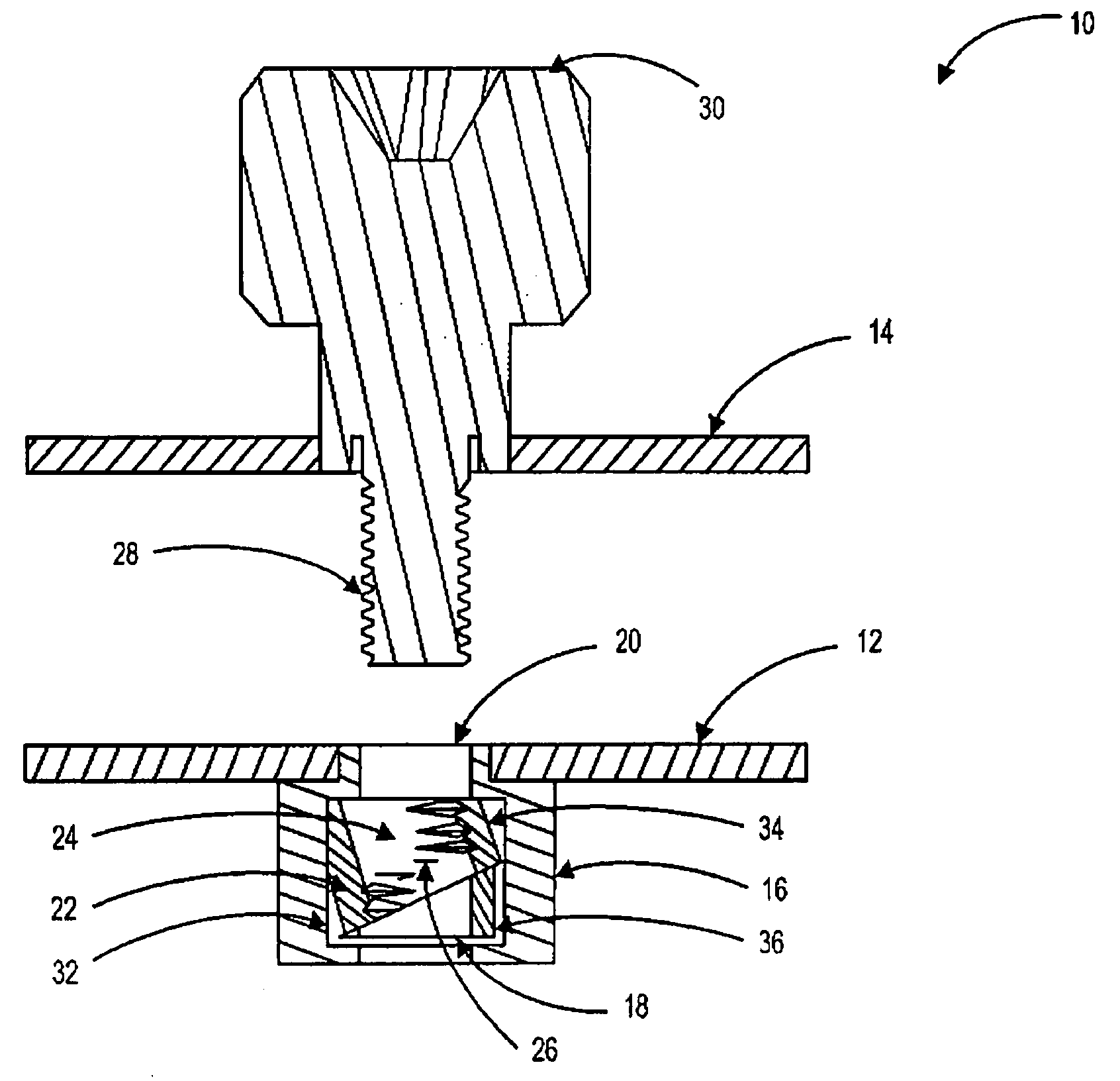
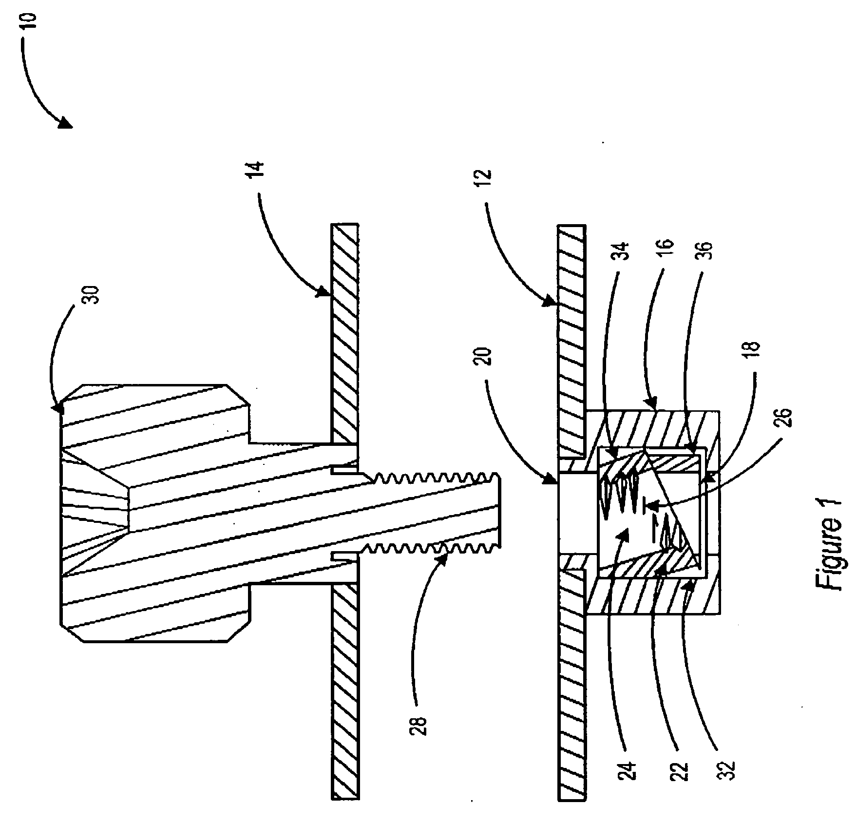
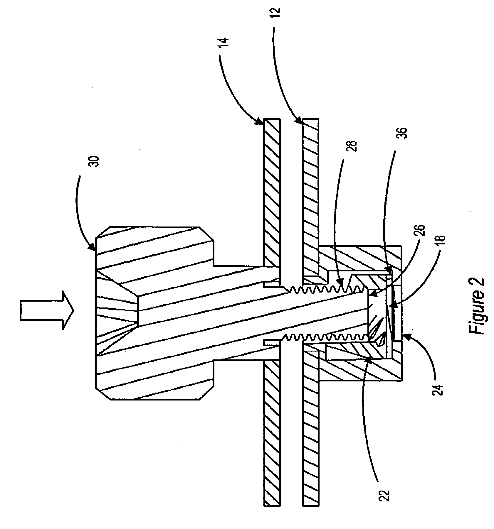
[0020] A push-in, screw out fastening apparatus simplifies the securing of devices to each other with a single push-in securing method while restricting separation of the devices from each other to unscrewing of the fastening apparatus. The push-in, screw out fastening apparatus aids in assembly of hot swappable modules in an information handling system and reduces risk of electric shock from disassembly of modules while power is applied to the information handling system. For purposes of this disclosure, an information handling system may include any instrumentality or aggregate of instrumentalities operable to compute, classify, process, transmit, receive, retrieve, originate, switch, store, display, manifest, detect, record, reproduce, handle, or utilize any form of information, intelligence, or data for business, scientific, control, or other purposes. For example, an information handling system may be a personal computer, a network storage device, or any other suitable device a...


PUM

PropertyMeasurementUnit
diameteraaaaaaaaaa
heightaaaaaaaaaa
timeaaaaaaaaaa

Abstract

A press-in fastening apparatus and method couples a screw with a nut by pushing the screw through an opening of the nut along a slip axis and rotating the nut to align a lock axis with the inserted screw. The opening of the nut along the slip axis has a diameter greater than the diameter of the screw and the opening of the nut along the lock axis has a diameter that engages screw threads with nut threads. In one embodiment, the nut is disposed in a housing coupled to an information handling system and biased to align with the lock axis so that a module is secured to the information handling system by aligning a screw coupled to the module with the nut and pushing the screw into the nut. The module is removed from the information handling system by unscrewing the screw with engagement of the screw threads and nut threads.

Description

BACKGROUND OF THE INVENTION [0001] 1. Field of the Invention [0002] The present invention relates in general to the field of fasteners, and more particularly relates to a rapid fastening screw apparatus and method. [0003] 2. Description of the Related Art [0004] As the value and use of information continues to increase, individuals and businesses seek additional ways to process and store information. One option available to users is information handling systems. An information handling system generally processes, compiles, stores, and / or communicates information or data for business, personal, or other purposes thereby allowing users to take advantage of the value of the information. Because technology and information handling needs and requirements vary between different users or applications, information handling systems may also vary regarding what information is handled, how the information is handled, how much information is processed, stored, or communicated, and how quickly a...

Claims


Application Information

Patent Timeline
Patent Type & Authority Applications(United States)
IPC IPC(8): F16B5/02F16B37/04F16B37/08
CPCF16B5/0208Y10T29/49963F16B37/0814F16B37/044
Inventor JONES, CHRISTOPHER A.BEALL, CHRISTOPHERIFFT, ALAN
Owner DELL PROD LP
Why Eureka
Try Eureka