Trusses for use in building construction and methods of installing same

a technology for building construction and trusses, applied in the direction of girders, joists, building roofs, etc., can solve the problems of increasing complexity, affecting the work efficiency of installers, and requiring a lot of skill which would otherwise be needed,

Active Publication Date: 2016-05-26
ILLINOIS TOOL WORKS INC
View PDF27 Cites 5 Cited by
  • Summary
  • Abstract
  • Description
  • Claims
  • Application Information

AI Technical Summary

Benefits of technology

[0009]According to another aspect of the present disclosure there is provided a fastening for coupling two components of a building structure comprising a first part for attachment to one of the components and a second part for attachment to the other of the component, the first and second parts each being of plate-like form, the first part providing a multiplicity of locking projections and the second part providing a multiplicity of apertures arranged in a configuration equivalent to that of the locking projections of the first part such that when the two parts are applied together in face-to-face relation the locking projections of the first part can extend through the apertures of the second part and lock to the second part to thereby lock the two parts together against separation of the two parts.

Problems solved by technology

Although construction of a roof from prefabricated trusses removes much of the skill which would otherwise be needed to construct a roof and, of course, enables relatively quick construction, nevertheless installing and fastening supplementary trusses within the main structure by installing to the face of a main truss for instance, can add a degree of complexity.
The environment in which the installers are working at roof level is not a stable environment and required “safe work practices” are not always adhered to.
Many of those working on site can be at risk until a main truss and its supplementary trusses are installed, temporarily braced, and made stable.
Additionally, issues sometimes issues arise through absence of adequate documentation for identification and accurate placement of the supplementary trusses.
A typical attachment consists of brackets fastened by nails to the top plate and bottom chord, itself quite a time consuming exercise carried out at roof level.

Method used


Image

  • Trusses for use in building construction and methods of installing same
  • Trusses for use in building construction and methods of installing same
  • Trusses for use in building construction and methods of installing same

Examples


Embodiment Construction

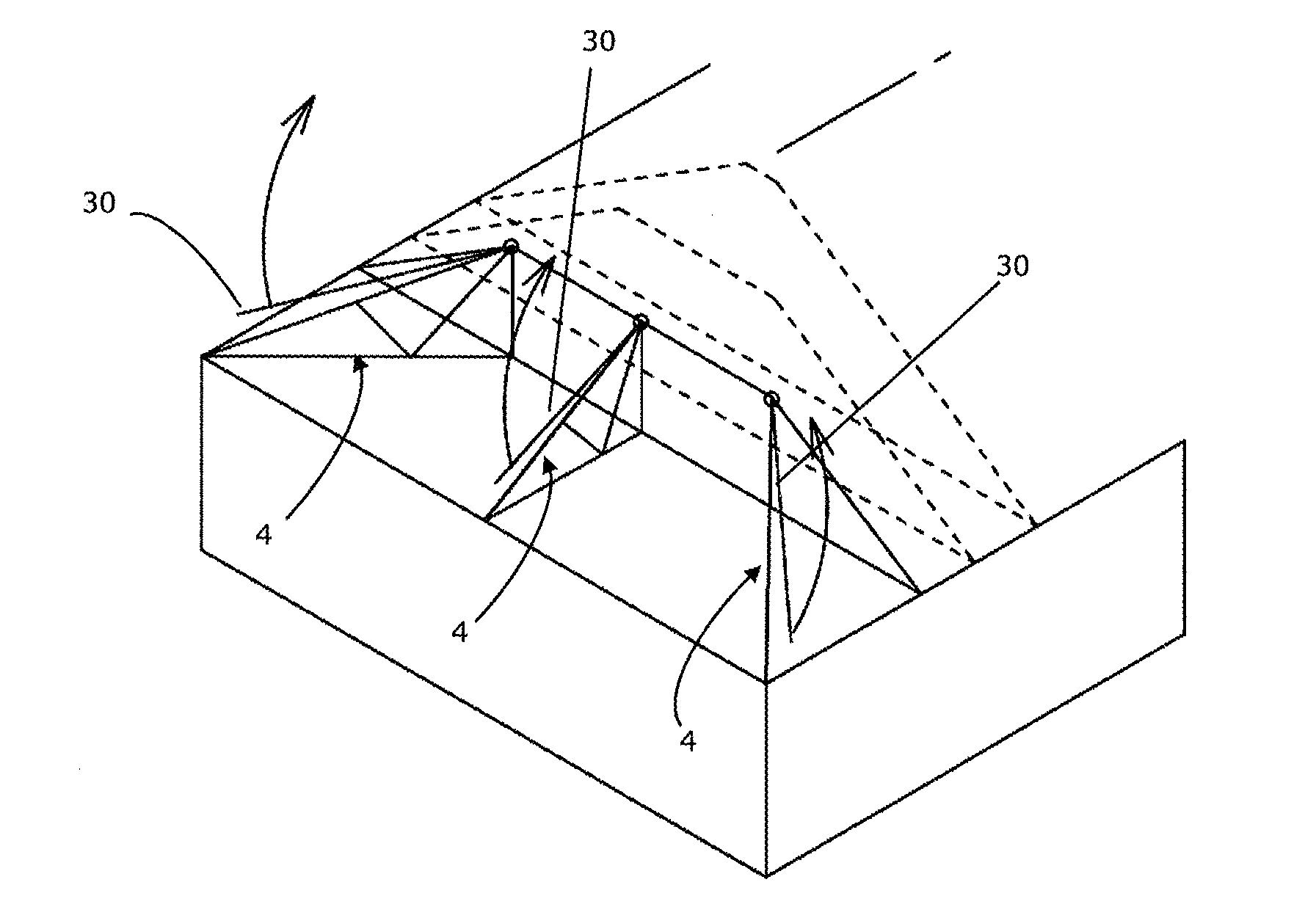
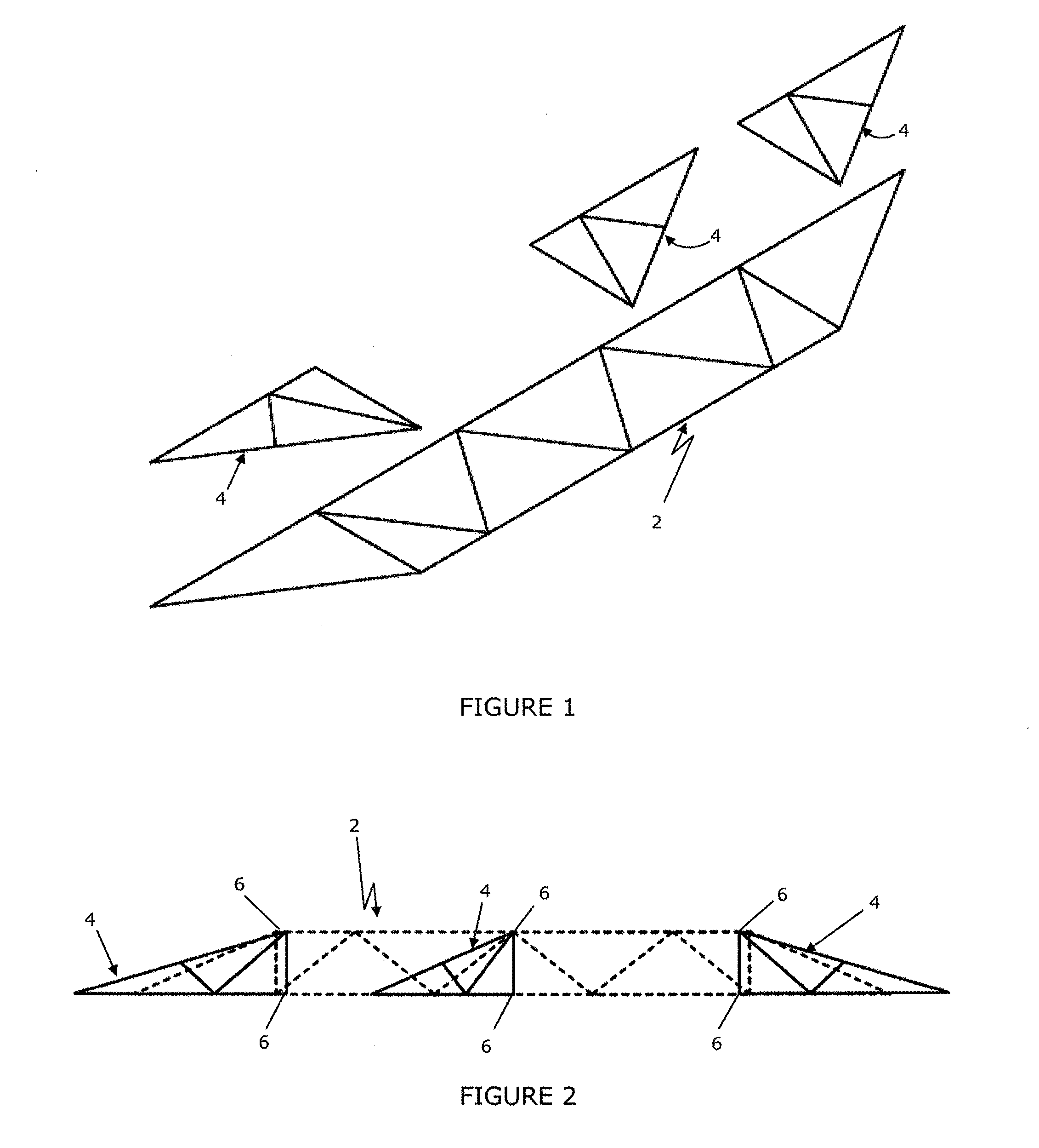
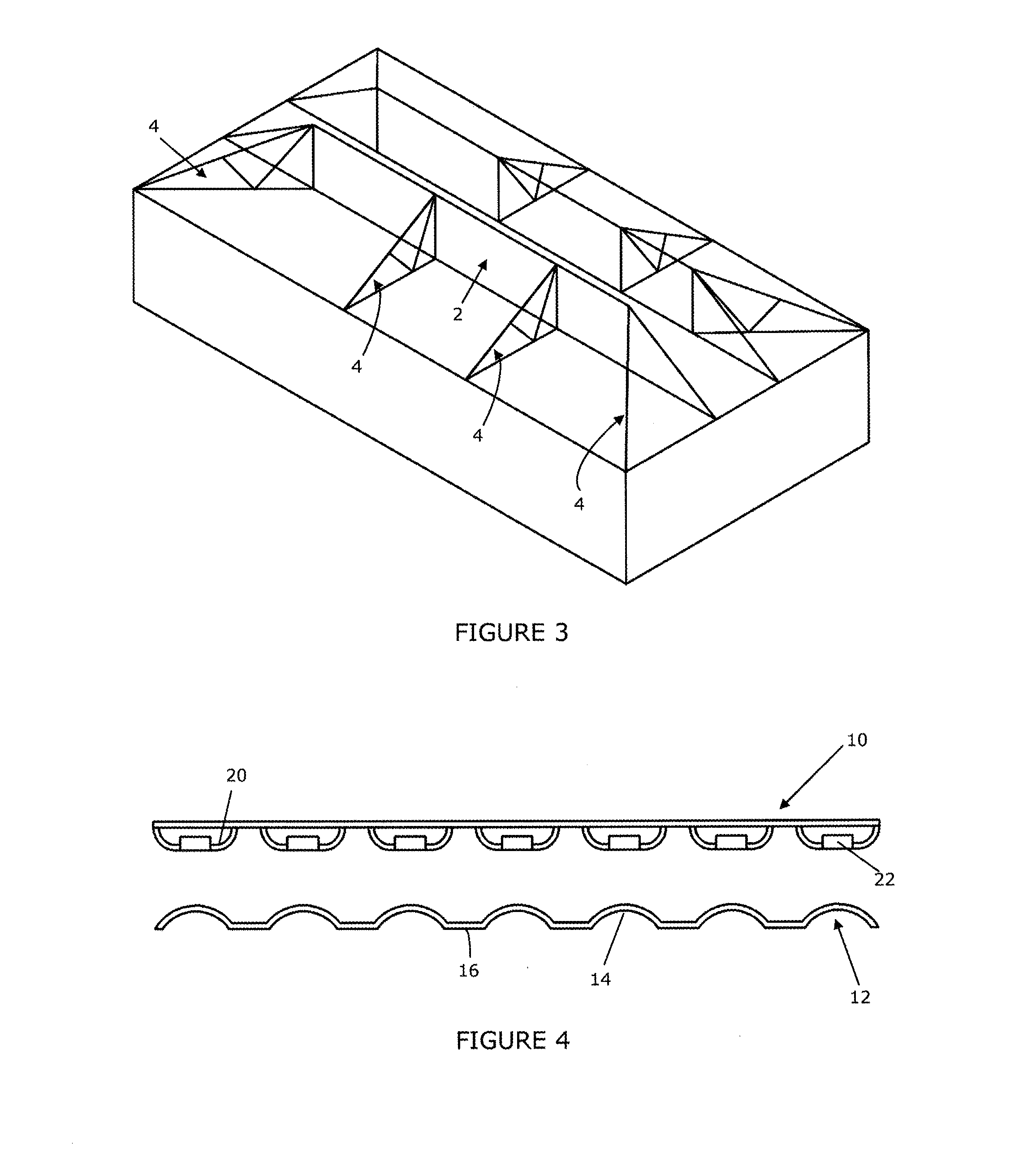
[0029]In an embodiment according to the first aspect of the present disclosure, prefabricated trusses which, in the assembled roof structure are to be attached to and extend transversely from another prefabricated truss, usually one of the larger trusses and which will be referred to for simplicity as a “main” truss are assembled to the main truss by hinges as part of the pre-fabrication process. The hinges provide a secure connection between the main truss and the other trusses, referred to for simplicity as “supplementary trusses”, and permit the supplementary trusses to be swung from a position in which a face of the supplementary truss lies adjacent a face of the main truss for transportation to site on the bed of a truck and lifting into position on site, typically by means of a crane. When the main truss is in position on the top plate or other underlying structure, the supplementary trusses can then be swung outwardly from the face of the main truss into its required orientat...


PUM


Abstract

A truss assembly for use in building construction, comprising a first truss and one or more second trusses attached to the first truss to extend transversely to a face of the first truss upon erection of the truss assembly, wherein the or each second truss is hingedly connected to the first truss for swinging movement about a substantially vertical axis between a folded configuration in which the second truss lies adjacent the face of the first truss and an erected configuration in which the second truss extends transversely to said face.

Description

PRIORITY CLAIM[0001]This application claims priority to and the benefit of: (1) Australian Patent Application No. 2014904787, filed on Nov. 26, 2014; and (2) Australian Patent Application No. 2015902094, filed on Jun. 2, 2015, the entire contents of each of which are incorporated herein by reference.BACKGROUND[0002]1. Field[0003]The present disclosure in one aspect relates to trusses in use for building construction, particularly in the construction of roofs. The disclosure in another aspect relates to the installation of a truss within the overall building structure.[0004]2. Description of the Prior Art[0005]In some types of building construction it is conventional practice to construct the roof using trusses prefabricated in a factory situation and transported to site for erection onto wall frames or other wall structure of the building. Although the main structure of a roof will normally be formed by a series of trusses arranged in spaced parallel relation, in the construction of...

Claims


Application Information

Patent Timeline
Patent Type & Authority Applications(United States)
IPC IPC(8): E04C3/02E04B7/06E04B1/41E04B7/02
CPCE04C3/02E04B1/40E04B7/063E04B7/022E04C3/11E04C3/17E04B1/38E04C2003/0486E04C2003/0495
Inventor KENNELLY, BERNARD JOSEPHPAULL, MICHAEL TIMOTHY
Owner ILLINOIS TOOL WORKS INC
Why Eureka
Try Eureka