
An Angle Adjustment Mechanism for Probing Rod at the Outer End of Wing

A technology of angle adjustment and probe rod, which is applied in the direction of aircraft parts, transportation and packaging, etc., can solve the problem that the equipment cannot be adjusted at any angle, and achieve the effect of small structure occupation, stable overall structure and convenient adjustment

Active Publication Date: 2017-09-26
HARBIN
View PDF4 Cites 0 Cited by
  • Summary
  • Abstract
  • Description
  • Claims
  • Application Information

AI Technical Summary

Problems solved by technology

This type of structure is stable in structure, easy to implement and easy to assemble, but the equipment cannot be adjusted at any angle
When installing some precision equipment such as exploration and testing on the probe rod, it is necessary to compensate the accumulated errors in assembly by changing the angle of the probe rod, or to adjust the relative position of the detection equipment to change the test data, the fixed support structure of the prior art It cannot meet the requirements of use, and a new scheme needs to be formulated

Method used


Image

  • An Angle Adjustment Mechanism for Probing Rod at the Outer End of Wing
  • An Angle Adjustment Mechanism for Probing Rod at the Outer End of Wing
  • An Angle Adjustment Mechanism for Probing Rod at the Outer End of Wing

Examples


Embodiment 1

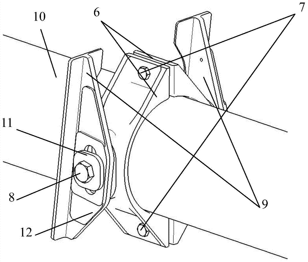
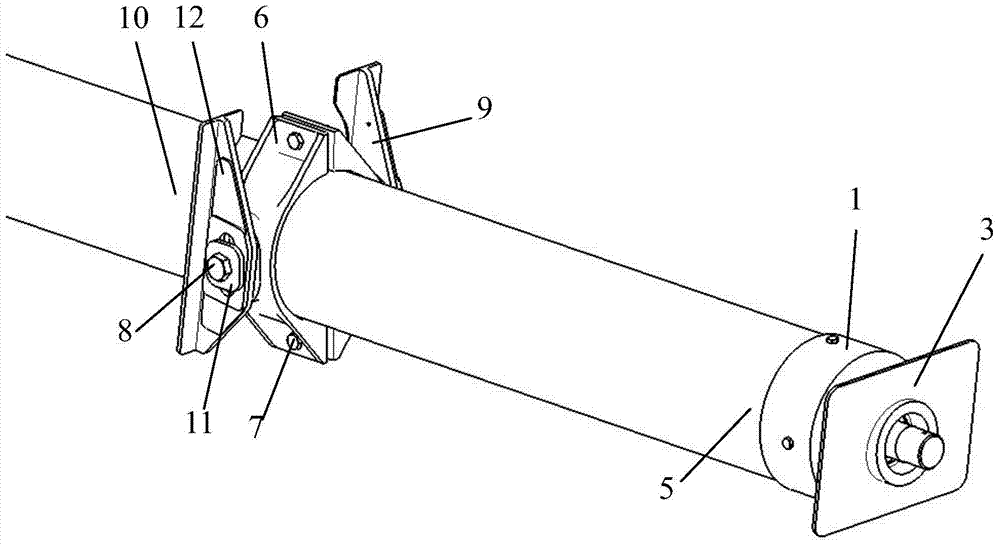
[0029] On the basis of specific implementation, the teeth of the toothed pad 11 and the tooth plate 12 are triangular teeth, and the tile cover 6 is semicircular. The movable space of the bolt II 8 processed on the bracket 9 and the tooth 12 is oblong when the probe rod is adjusted. L is 1 mm, R is 555 mm, and α is calculated to be 0.1°, that is, every time the toothed pad 11 and the tooth plate 12 move a sawtooth, the probe rod rotates 0.1°; when the middle part 10 of the probe rod is adjusted to a proper position, the lock Tighten the bolt II 8, the teeth of the toothed pad 11 and the tooth plate 12 are engaged, and the middle part 10 of the probe rod is limited, and the fixation of the probe rod after angle adjustment is completed.


PUM


Abstract

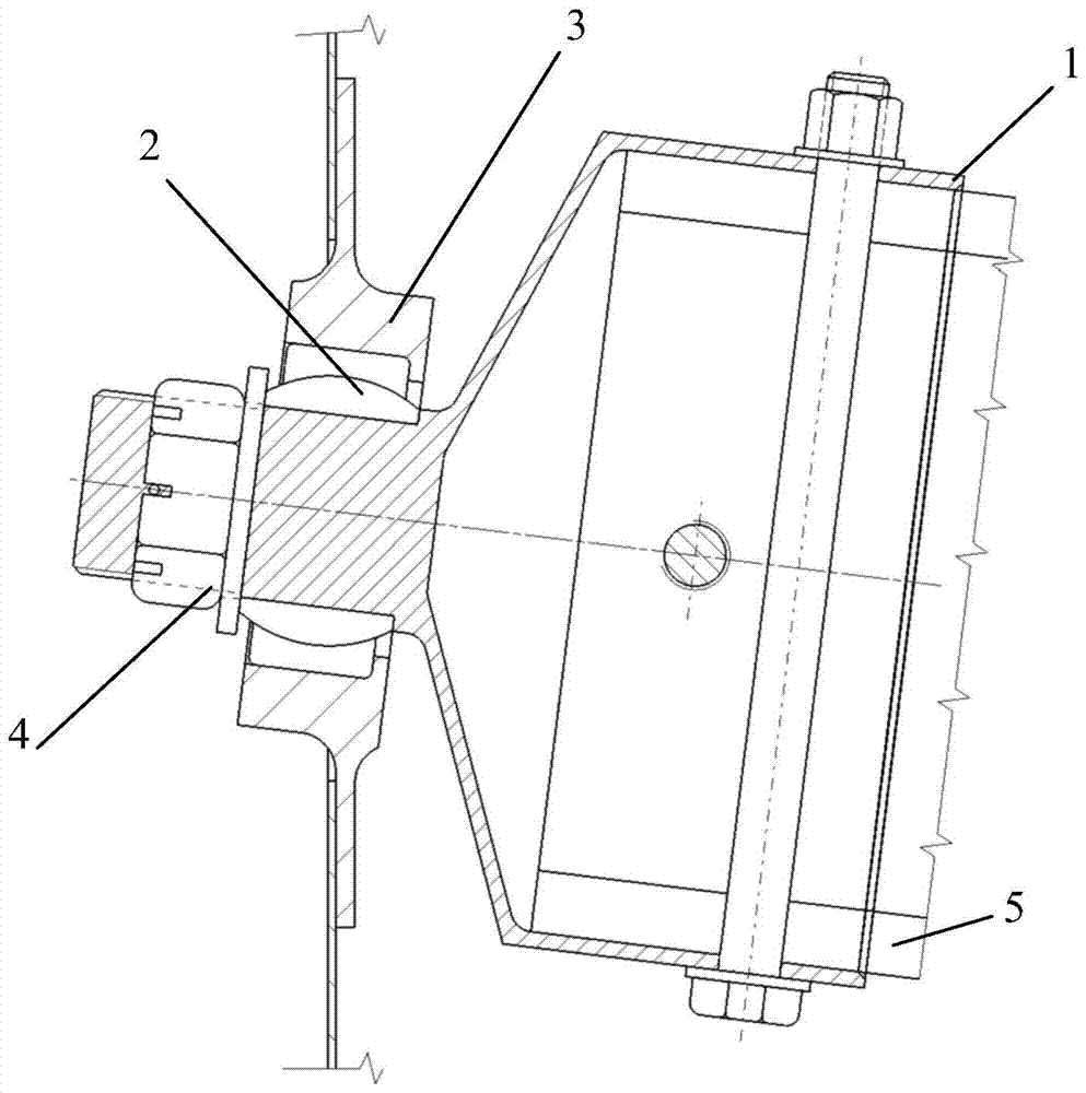
The invention relates to an angle adjustment mechanism for a probe rod at the outer end of a wing, which consists of a probe rod joint (1), a joint bearing (2), a bearing support (3), a nut (4), a probe rod end (5), Tile cover (6), bolt I (7), bolt II (8), bracket (9), middle part of the probe rod (10), toothed pad (11), and tooth plate (12), the middle part of the probe rod 10 is adjusted to When the position is proper, the locking bolt II 8, the serrations of the toothed pad 11 and the tooth plate 12 are engaged to limit the position of the middle part 10 of the probe rod, and the fixation of the probe rod after angle adjustment is completed. The invention can not only meet the requirement of adjusting the angle of the probe rod, but also can completely fix the probe rod when the adjustment position is proper.

Description

technical field [0001] The invention relates to a structure design of a fixed-wing aircraft, and is especially suitable for the design of a probe rod at the outer end of the wing. Background technique [0002] At present, adding equipment to the wing of a fixed-wing aircraft has been modified in a variety of ways, and the technology is relatively mature. Installing an overhanging probe rod at the outer end of the wing is also one of the common solutions in the modification. The common structural form is at the outer end of the wing. The fixed support is connected to the two ribs with a suitable span, and the probe rod is fixed with the screwed tile cover, and it is completely fixed with bolts. This type of structure is stable in structure, easy to implement, and convenient to assemble, but the equipment cannot be adjusted at any angle. When installing some precision equipment such as exploration and testing on the probe rod, it is necessary to compensate the accumulated err...

Claims


Application Information

Patent Timeline
Patent Type & Authority Patents(China)
IPC IPC(8): B64D47/00
Inventor 陈洲蛟万昌俊张余
Owner HARBIN
Learn More