Method and system for detecting bandwidth, and devices
A bandwidth and bandwidth request message technology, applied in the field of computer networks, can solve the problems of occupying network resources, time-consuming, and cumbersome detection process.
- Summary
- Abstract
- Description
- Claims
- Application Information
AI Technical Summary
Problems solved by technology
Method used
Image
Examples
Embodiment 1
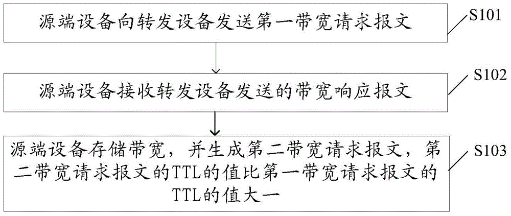
[0048] An embodiment of the present invention provides a method for detecting bandwidth, such as figure 1 Shown is a schematic flow chart of the method, specifically including:
[0049] S101. The source device sends a first bandwidth request packet to the forwarding device.
[0050] The destination Internet Protocol (English: Internet Protocol, abbreviation: IP) address of the first bandwidth request message is the IP address of the destination device. The forwarding device is other devices on the network link detected by the source device except the source device, including all forwarding devices and destination devices passed between the source device and the destination device. On an actual network link, the forwarding device can be a router or a Layer 3 switch.
[0051] It should be noted that the first bandwidth request message includes a time to live (English: TimetoLive, abbreviation: TTL) of the first bandwidth request message. The first bandwidth request message is...
Embodiment 2
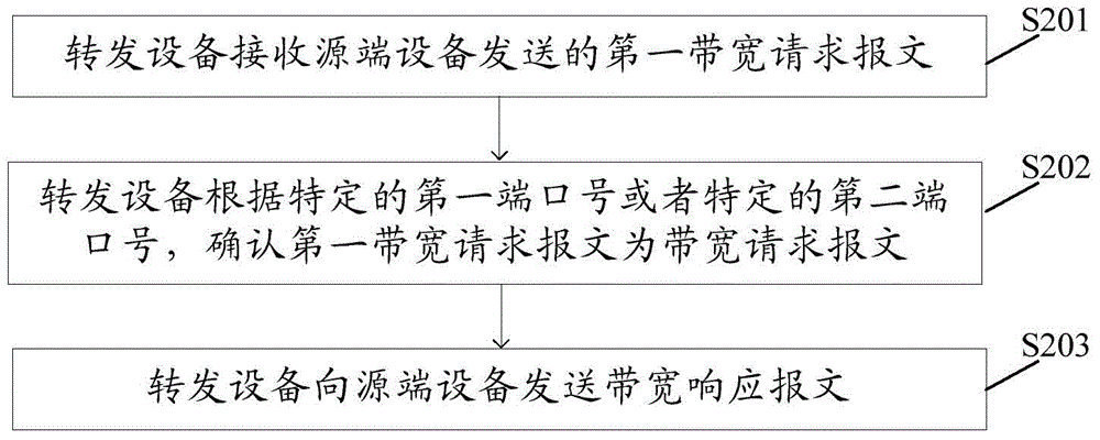
[0075] An embodiment of the present invention provides a method for detecting bandwidth, such as figure 2 Shown is a schematic flow chart of the method, specifically including:
[0076] S201. The forwarding device receives the first bandwidth request message sent by the source device.
[0077] The destination IP address of the first bandwidth request message is the IP address of the destination device, and when the first bandwidth request message is a UDP type message, the UDP type message includes a specific first port number, and the specific first port number is used When the forwarding device recognizes that the UDP type message is a bandwidth request message, or the first bandwidth request message is a TCP type message, the TCP type message includes a specific second port number, and the specific second port number is used by the forwarding device The TCP type message is identified as the bandwidth request message, and the TTL value in the first bandwidth request messag...
Embodiment 3
[0120] An embodiment of the present invention provides a source device, such as Figure 4 Shown is a schematic structural diagram of the source device, including:
[0121] The sending module 10 is configured to send a first bandwidth request message to the forwarding device, where the destination IP address of the first bandwidth request message is the IP address of the destination device.
[0122] The receiving module 11 is configured to receive a bandwidth response message sent by the forwarding device, wherein the bandwidth response message includes the IP address and bandwidth of the forwarding device, and the bandwidth is the bandwidth between the forwarding device and the next-hop forwarding device of the forwarding device.
[0123] The execution module 12 is configured to store the bandwidth and generate a second bandwidth request message, where the TTL value of the second bandwidth request message is one greater than the TTL value of the first bandwidth request message...
PUM
 Abstract
Description
Claims
Application Information
 - R&D
- Intellectual Property
- Life Sciences
- Materials
- Tech Scout
- Unparalleled Data Quality
- Higher Quality Content
- 60% Fewer Hallucinations
Browse by: Latest US Patents, China's latest patents, Technical Efficacy Thesaurus, Application Domain, Technology Topic, Popular Technical Reports.
© 2025 PatSnap. All rights reserved.Legal|Privacy policy|Modern Slavery Act Transparency Statement|Sitemap|About US| Contact US: help@patsnap.com


