Operative site marking device
A technology for identifying devices and parts, which is applied in the fields of surgery, medical science, diagnosis, etc. It can solve the discomfort and unpleasantness of patients, and achieve the effects of avoiding discomfort and unpleasantness, improving comfort, and facilitating safety inspections
- Summary
- Abstract
- Description
- Claims
- Application Information
AI Technical Summary
Problems solved by technology
Method used
Image
Examples
Embodiment 1
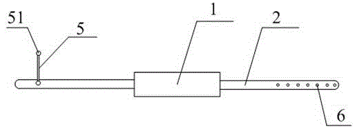
[0036] Such as figure 1 As shown, a surgical site identification device includes an identification box 1 and wristbands 2 connected to both sides of the identification box 1. The identification box 1 is provided with an identification mechanism 3 for the doctor to mark the patient's surgical site. In this embodiment, The identification mechanism 3 is a concave-convex model imitating the human body. figure 1 is a top view of the surgical site identification device.
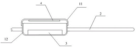
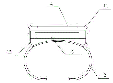
[0037] Such as figure 2 as shown, figure 2It is a longitudinal sectional view of the logo box 1, the logo box 1 includes a box body 12 and an upper cover 11 covered on the box body 12, the upper end of the box body 12 is open, and the imitation human body concave-convex model is located in the box body 12 , the patient information card 4 is arranged inside the upper cover 11 , and the box body 12 is connected with the wristband 2 . The patient information card 4 is used to fill in the basic information of the...
Embodiment 2
[0049] On the basis of Embodiment 1, the identification box 1 is further improved in this embodiment:
[0050] Such as Figure 5 As shown, the box body 12 is provided with a fixing mechanism for fixing the concave-convex model of the imitation human body, and the bottom surface of the box body 12 in the box body 12 is provided with a model groove 121 for placing the concave-convex model of the imitation human body and an installation groove 122 for installing the fixing mechanism. The fixing mechanism includes a screw rod 15 and a fixing block 16; the model groove 121 and the installation groove 122 are arranged side by side on the left and right, and there is an isolation part 123 in the middle, the installation groove 122 is located on the left side of the isolation part 123, and the model groove 121 is located on the right side of the isolation part 123 Side, the right side wall of the model groove 121 is provided with a limit block 17; the isolation part 123 is provided wi...
Embodiment 3
[0055] On the basis of Embodiment 1, the logo box 1 is further improved in this embodiment: the imitation human body concave-convex model is pasted on the bottom of the box body 12, for example but not limited to a movable Glue, one side of the removable glue is pasted on the downward side of the imitation human body concave-convex model, and the other side is removably pasted on the bottom of the box body 12. This is convenient for doctors to replace the imitation human body concave-convex model. In this embodiment, the bottom of the box body 12 refers to the bottom surface inside the box body 12 .
PUM
 Abstract
Description
Claims
Application Information
 - R&D
- Intellectual Property
- Life Sciences
- Materials
- Tech Scout
- Unparalleled Data Quality
- Higher Quality Content
- 60% Fewer Hallucinations
Browse by: Latest US Patents, China's latest patents, Technical Efficacy Thesaurus, Application Domain, Technology Topic, Popular Technical Reports.
© 2025 PatSnap. All rights reserved.Legal|Privacy policy|Modern Slavery Act Transparency Statement|Sitemap|About US| Contact US: help@patsnap.com


