Wire harness sheet metal riveting equipment and use control method

A control method and sheet metal technology, applied in the field of wire harness sheet metal riveting, can solve the problems of high labor intensity and unqualified products in wire harness sheet metal riveting, and achieve the effects of reliable riveting quality, simple use and good stability.

Active Publication Date: 2017-07-28
宁波拓普电器有限公司
View PDF5 Cites 6 Cited by
  • Summary
  • Abstract
  • Description
  • Claims
  • Application Information

AI Technical Summary

Problems solved by technology

[0003] The purpose of the present invention is to solve the problem that the existing wire harness sheet metal riveting is done manually, resulting in high labor intensity and prone to the shortage of unqualified wire harness sheet metal riveting products. The quality of gold riveting is reliable, the degree of intelligence is high, the stability is good, and the use of simple wiring harness sheet metal riveting equipment and its use control method

Method used


Image

  • Wire harness sheet metal riveting equipment and use control method
  • Wire harness sheet metal riveting equipment and use control method
  • Wire harness sheet metal riveting equipment and use control method

Examples


Embodiment 1

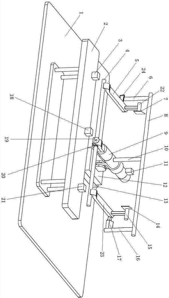
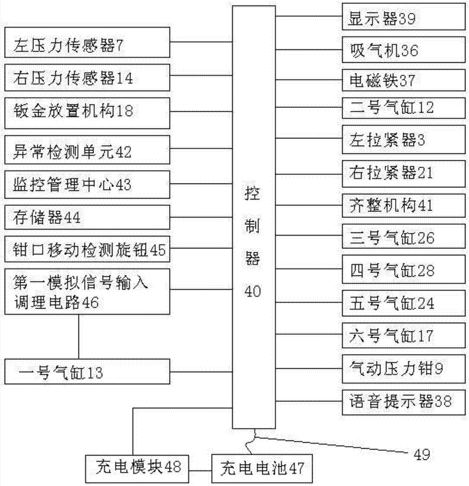
[0024] Example 1: Wire harness sheet metal riveting equipment, see figure 1 , figure 2 , image 3 , Image 6 As shown, it includes a platform 1 and a controller 40, as well as a voice prompt 38 and a display 39 respectively connected to the controller. The No. 1 cylinder 13 is fixed on the platform, and the No. 1 telescopic rod of the No. 1 cylinder is arranged to move horizontally back and forth; No. 2 cylinder 12 is fixed on the No. 1 telescopic rod of the No. 1 cylinder, and the No. 2 telescopic rod of the No. 2 cylinder is arranged vertically up and down; the No. 2 telescopic rod of the No. 2 cylinder is fixed horizontally and forwards. Pneumatic pressure pliers 9 and the jaws 25 of the pneumatic pressure pliers are arranged forward; on the platform in front of the jaws of the pneumatic pressure pliers, there is a tooling fixing table 2; the left and right ends of the tooling fixing table are respectively provided with a wire harness capable of tensioning The left tensione...

Embodiment 2

[0026] Example 2, see figure 1 , figure 2 , image 3 , Figure 4 As shown, the difference between Embodiment 2 and Embodiment 1 lies in. A sheet metal placing mechanism 18 is provided on the tooling fixed platform between the left tensioner and the right tensioner, and the sheet metal placing mechanism is arranged on the tooling fixed platform directly in front of the jaws. The control end of the sheet metal placing mechanism is connected with The controller is connected; the sheet metal placement mechanism includes the No. 3 cylinder 26 fixedly arranged on the tooling fixing table, the No. 4 cylinder 28 fixedly arranged on the No. 3 telescopic rod 27 of the No. 3 cylinder, and the No. 4 cylinder fixedly arranged on the No. 4 cylinder The sheet metal placer on the telescopic rod 29, and the third telescopic rod of the third cylinder is arranged vertically upwards, the fourth telescopic rod of the fourth cylinder is arranged toward the jaws of the pneumatic pressure clamp, and t...

Embodiment 3

[0028] Example 3, see figure 1 , figure 2 , image 3 , Figure 5 As shown, the difference between Embodiment 3 and Embodiment 2 lies in. The sheet metal placer includes an electromagnet 37, hanging nails and an "L"-shaped placing block fixedly arranged on the No. 4 telescopic rod. The placing block includes a vertical block arranged vertically and a horizontal block arranged horizontally. The hanging nails are set On the vertical block on the side of the horizontal block, the electromagnet is arranged on the horizontal block, and the control end of the electromagnet is connected with the controller.

[0029] When the embodiment 3 is in use, its use control method is as follows: the user first clamps the two ends of a wire harness covered with a sheath and sheet metal on the sheath to the left tensioner and the right tensioner. Use the mounting holes on the sheet metal to hang the sheet metal on the pegs of the sheet metal placer; then under the command of the controller, start t...


PUM


Abstract

The invention discloses harness metal plate riveting equipment and a use and control method and relates to the technical field of harness metal plate riveting. The equipment can be used for riveting a metal plate on a harness and can carry out abnormity detection, and is reliable in harness metal plate riveting quality, high in intelligent degree and simple to use. The equipment comprises a platform, a voice prompter, a display and a controller, wherein a cylinder I is arranged on the platform, a cylinder II is arranged on a telescopic rod I of the cylinder I, a pneumatic pressure clamp is arranged on the telescopic rod II of the cylinder II, a tool fixing platform is arranged on the platform in front of the jaw of the pneumatic pressure clamp; the equipment further comprises a trimming mechanism for aligning a sheath on the harness to a metal plate on the harness left and right; and the control end of the cylinder I, the control end of the cylinder II, the control end of the pneumatic pressure clamp, the control end of a left tensioner, the control end of a right tensioner and the control end of the trimming mechanism are respectively connected with a controller.

Description

Technical field [0001] The invention relates to the technical field of wire harness sheet metal riveting and pressing, in particular to wire harness sheet metal riveting equipment and a use control method. Background technique [0002] At present, the riveting of sheet metal on the wire harness is generally carried out manually, with low production efficiency and high labor intensity, and unqualified products of the riveting of wire harness sheet metal are prone to appear. Therefore, it is very necessary to design a wire harness sheet metal riveting equipment with high qualification rate and stable and reliable product quality. Summary of the invention [0003] The invention aims to solve the problem that the existing wire harness sheet metal riveting is carried out manually, which results in high labor intensity and easy to appear unqualified products of the wire harness sheet metal riveting, and provides a riveting and pressing of the sheet metal on the wire harness. The qualit...

Claims


Application Information

Patent Timeline
Patent Type & Authority Patents(China)
IPC IPC(8): B21D39/00H01R43/048
CPCB21D39/00H01R43/048
Inventor 叶志伟刘俊华
Owner 宁波拓普电器有限公司
Why Eureka
Try Eureka