Riveting machine for rivets

A riveting machine and rivet technology, applied in the field of rivet riveting machines, can solve the problems of complex structure, poor riveting effect and high equipment cost, and achieve the effects of low equipment cost, high riveting quality and simple structure

Inactive Publication Date: 2012-05-02
徐州宇家化工科技有限公司
View PDF0 Cites 6 Cited by
  • Summary
  • Abstract
  • Description
  • Claims
  • Application Information

AI Technical Summary

Problems solved by technology

[0002] At present, the rivet riveting machine generally adopts the stamping type of work, that is, through the crank connecting rod transmission mechanism, it is converted into a linear motion mechanism, and the linear motion mechanism drives the riveting head to realize the riveting of the rivet. This kind of riveting machine exists. The structure is complex and the equipment cost is high. At the same time, because the riveting mechanism only produces a stamping action on the head of the rivet, there is also the defect that the riveting effect is poor

Method used


Image

  • Riveting machine for rivets
  • Riveting machine for rivets

Examples


Embodiment Construction

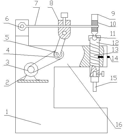
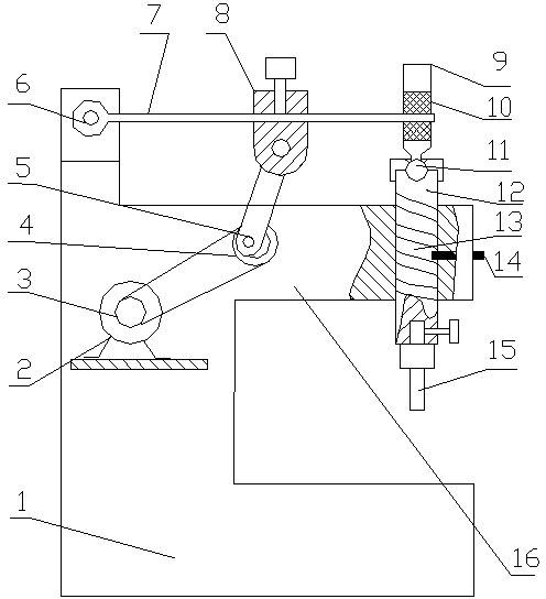
[0009] The fuselage 1 has a protruding cantilever 16, a guide rod 12 is installed vertically at the end of the cantilever 16, and a similar helical cam groove 13 is arranged on the outer circle of the guide rod 12, and the pin shaft 14 is installed and fixed on the cantilever 16. At the end, the inner end of the pin shaft 14 is engaged in the cam groove 13, and a riveting joint 15 is installed and fixed at the bottom end of the guide rod 12, and the ball connecting rod 9 is hinged to the top of the guide rod 12 through the ball joint 11 thereon. Together, a rubber pad 10 is inlaid in the cavity inside the middle of the ball connecting rod 12, one end of the elastic plate 7 is hinged with the top of the fuselage 1 by a rotating shaft 6, and the other end of the elastic plate 7 is inserted into the rubber pad 10 , an adjustable seat 8 is provided on the elastic plate 7, an eccentric disk 4 is arranged on the fuselage 1, an eccentric shaft is arranged on the eccentric disk 4, and ...


PUM


Abstract

A riveting machine for rivets mainly comprises a body, a motor, a motor wheel, an eccentric wheel, a connecting rod, a rotating shaft, an elastic plate, an adjusting seat, a ball connecting rod, a rubber pad, a guide rod and a riveting head. An eccentric disk is driven by the motor to drive the connecting rod, the connecting rod drives the elastic plate to rotate around the rotating shaft, the elastic plate drives the guide rod to move vertically, a cam slot is arranged on the guide rod, a pin is mounted on the body, and the inner end of the pin is clamped in the cam slot. Therefore, the guide rod rotates to a certain degree while moving vertically, and then drives the riveting head to spin the rivets. The riveting machine has the advantages of simple structure, lower cost and higher quality of riveting for the rivets.

Description

technical field [0001] The invention relates to a rivet riveting machine, belonging to the technical field of rivet riveting machines. Background technique [0002] At present, the rivet riveting machine generally adopts the stamping type of work, that is, through the crank connecting rod transmission mechanism, it is converted into a linear motion mechanism, and the linear motion mechanism drives the riveting head to realize the riveting of the rivet. This kind of riveting machine exists. The structure is complex and the equipment cost is high. At the same time, because the riveting mechanism only produces a stamping action on the head of the rivet, there is also the disadvantage of poor riveting effect. Contents of the invention [0003] The object of the present invention is to provide a new type of riveting machine to overcome the above-mentioned defects in the existing riveting machine. [0004] The technical solution adopted by the present invention to achieve the a...

Claims


Application Information

Patent Timeline
Patent Type & Authority Applications(China)
IPC IPC(8): B21J15/26
Inventor 钟帆
Owner 徐州宇家化工科技有限公司
Why Eureka
Try Eureka