Positioning clamp

A positioning clamping and positioning plate technology, applied in the direction of clamps, manufacturing tools, etc., can solve the problems of time-consuming and laborious, troublesome disassembly and assembly of plates, and movement, and achieve the effect of preventing movement, disassembly and assembly, and preventing wear

Inactive Publication Date: 2016-06-15
黄斌
View PDF6 Cites 3 Cited by
  • Summary
  • Abstract
  • Description
  • Claims
  • Application Information

AI Technical Summary

Problems solved by technology

Some of the existing technologies use manual fixing of rectangular plates. On the one hand, this fixing method is time-consuming and laborious;
Others use positioners to position the plates, but the existing positioners are cumbersome to disassemble and assemble the plates on the one hand, and on the other hand cannot meet the needs of plates of different sizes.

Method used


Image

  • Positioning clamp
  • Positioning clamp
  • Positioning clamp

Examples


Embodiment Construction

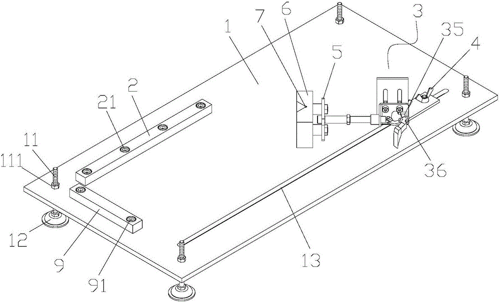
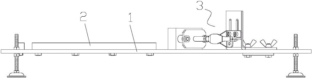
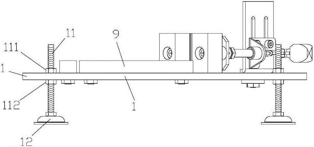
[0026] Such as Figure 1-Figure 5 As shown, the positioning clamp includes a bottom plate 1, the bottom plate 1 is a cuboid structure, and threaded holes are processed at the four corners of the bottom plate 1, and the threaded holes penetrate from the upper surface of the bottom plate 1 to the bottom of the bottom plate 1 surface. Support screw rod 11 is installed in each threaded hole, and support base 12 is vertically installed on the lower surface of each support screw rod 11, and the lower surface of support base 12 is planar structure, and described support screw rod 11 passes threaded hole, and Each support screw 11 is threadedly equipped with a tightening nut A111 and a tightening nut B112, the lower surface of the tightening nut A111 is against the upper surface of the bottom plate 1, and the upper surface of the tightening nut B112 is against the upper surface of the base plate 1. The lower surface of the base plate 1 is fixed on the base plate 1 by the support scre...


PUM


Abstract

The invention discloses a positioning clamp, comprising a bottom plate, a strip groove is processed along the length direction of the bottom plate, a long positioning plate and a short positioning plate are installed on the bottom plate, and a clamping structure is installed in the strip groove. The clamping structure includes a clamping moving plate, a folded mounting plate, a crank, a rocker, and a positioning clamping seat. A triangular positioning groove is provided at the middle position of an end surface of the positioning clamping seat, and a corner of the triangular positioning groove An anti-skid groove is provided at the place, and an anti-skid pad is installed in the anti-skid groove. On the one hand, the present invention can satisfy the positioning of rectangular plates of different sizes and prevent movement; on the other hand, it saves time and labor in disassembly and assembly comparison.

Description

technical field [0001] The invention belongs to the technical field of plate clamping, in particular to a positioning clamp for rectangular plates. Background technique [0002] At present, when people process the surface of a rectangular plate, it is necessary to clamp the rectangular plate to prevent it from moving, and then use tools to process the surface. Some of the existing technologies use manual fixing of the rectangular plates. On the one hand, this fixing method is time-consuming and labor-intensive; Some also use a locator to locate the plates, but the existing locators are cumbersome to disassemble and assemble the plates on the one hand, and on the other hand cannot meet the plates of different sizes. Contents of the invention [0003] In order to overcome the deficiencies in the prior art, the present invention provides a positioning clamp. On the one hand, it can meet the positioning of rectangular plates of different sizes and prevent movement. On the oth...

Claims


Application Information

Patent Timeline
Patent Type & Authority Applications(China)
IPC IPC(8): B25B5/14B25B5/16
CPCB25B5/003B25B5/145B25B5/163
Inventor 黄斌
Owner 黄斌
Why Eureka
Try Eureka