A high-frequency longitudinal-torsion composite vibrating sponge array strip-taking device and its application

A compound vibration and longitudinal torsion technology, which is applied in metal processing and other directions, can solve the problems of inability to process multiple pieces at the same time, difficult strip control, low efficiency, etc., and achieve the effect of expanding the scope of use, broad market prospects, and simple device structure

Inactive Publication Date: 2017-10-24
SUZHOU UNIV OF SCI & TECH
View PDF10 Cites 0 Cited by
  • Summary
  • Abstract
  • Description
  • Claims
  • Application Information

AI Technical Summary

Problems solved by technology

[0006] The invention provides a high-frequency longitudinal-torsion composite vibration sponge array strip-taking device, which is used to solve the current problems of difficult control, low efficiency, pollution, and inability to process multiple pieces at the same time on sponge-like elastic bodies.

Method used


Image

  • A high-frequency longitudinal-torsion composite vibrating sponge array strip-taking device and its application
  • A high-frequency longitudinal-torsion composite vibrating sponge array strip-taking device and its application
  • A high-frequency longitudinal-torsion composite vibrating sponge array strip-taking device and its application

Examples


Embodiment 1

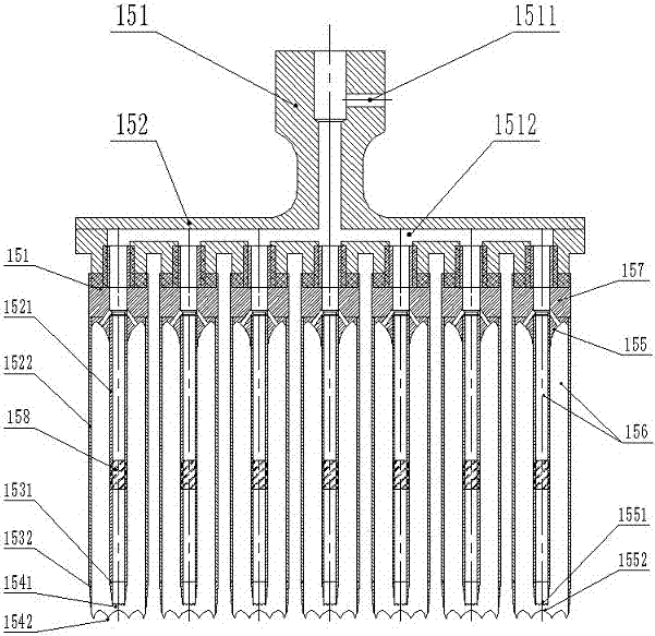
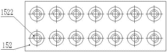
[0046] Such as figure 2 and image 3 As shown, the multi-tube cutter 15 includes a connecting head 151 connected to the horn 14, a pipe body mounting plate 152 connected to the connecting head 151, and an internal cavity 156 is set on the pipe body mounting plate 152 The inner layer tube body 1521 and the outer layer tube body 1522, the inner cutting edge 1531 and the outer cutting edge 1532.

[0047] Continue to see figure 2 and image 3 One end of the inner tube body 1521 and the outer tube body 1522 containing the cavity 156 is threadedly connected with the tube body installation plate 152, and the other end is welded to the inner cutting edge 1531 and the outer cutting edge 1532, and the inner layer The inner diameter of the tube body 1521 is 5 mm, the inner diameter of the outer layer tube body 1522 is 12 mm, the tube walls of the inner layer tube body 1521 and the outer layer tube body 1522 are both 1 mm, and the materials of the inner layer tube body 1521 and the o...

Embodiment 2

[0060] The difference from Embodiment 1 is that the tube body mounting plate 152 also includes a cover 1523 for the internally threaded hole 1522 . It is used for the closure of the internally threaded hole 1522 that is not connected to the pipe body 156 .

[0061] For example, when the inner and outer diameters of the pre-processed cylindrical hollow strip blank are relatively large, such as Figure 7 As shown, the external thread head 1533 of the pipe body 156 matches the internal thread hole 1522, and the cavity 153 matches the size of the pre-processed hole.

[0062] Since the outer diameter of the tube becomes larger, the tubes cannot be sequentially arranged on the tube mounting plate 152 , and the unused internal threaded hole 1522 is closed by the cover 1523 .

[0063] Using the processing process described in Embodiment 1, the processing of multiple cylindrical hollow strip blanks 23 can be realized.


PUM


Abstract

The invention particularly relates to a high-frequency longitudinal-torsional composite vibration sponge array strip cutting device and application. The device comprises an ultrasonic generator, an ultrasonic transducer, at least one stage of amplitude change bar and a multi-pipe tool; the multi-pipe tool is connected with the amplitude change bar through a thread and comprises a connector connected with the amplitude change bar, a pipe body arranging plate connected with the connector, multiple pipe bodies which contain cavities and arranged on the pipe body arranging plate and cutting edges, wherein one end of each pipe body is detachably connected with the pipe body arranging plate, the other end of each pipe body extends out of the corresponding cutting edge, and each pipe body is provided with a longitudinal-torsional composite vibration conversion structure. According to the device, strip cutting is easily performed on a sponge in a high-frequency vibration mode, multi-hole forming operation is achieved through the design of the pipe body arranging plate, pipe body replacement is convenient through a detachable connection mode, therefore, the using range is greatly widened, the production efficiency can be obviously improved, and the structure is simple.

Description

technical field [0001] The invention belongs to the sponge processing technology, and in particular relates to a high-frequency longitudinal-torsion compound vibration sponge array strip-taking device, which is mainly used for processing the elastic body layer on the transfer roller in a printing copier. Background technique [0002] In daily life or industrial products, there are many cases where chipping processing is required on elastic materials such as artificial sponge, foam rubber, etc., but the above materials are easily deformed under slight pressure or torsion and tend to resist movement through compression or deformation. cutting or drilling action. [0003] The transfer roller of a printer or copier generally includes a metal mandrel and an elastomer layer sleeved outside the metal mandrel. The elastomer layer is usually the above-mentioned elastic material. In order to set the inner mandrel, holes need to be opened on the elastic material. . The transfer rolle...

Claims


Application Information

Patent Timeline
Patent Type & Authority Patents(China)
IPC IPC(8): B26D1/06B26D7/08B26D7/18B26D7/26
CPCB26D1/0006B26D1/06B26D7/086B26D7/1854B26D7/2614B26D2001/006B26D2007/013
Inventor 殷振钱蜜汪帮富齐芳娟伯洁杨鑫铭张磊刘嵚昀黄开明吴雷
Owner SUZHOU UNIV OF SCI & TECH
Why Eureka
Try Eureka