A high-frequency vibrating sponge array strip-taking device and its application

A high-frequency vibration and sponge technology, applied in metal processing, etc., can solve the problems of simultaneous multi-hole processing, difficulty in strip control, pollution, etc., and achieve the effects of expanding the scope of use, broad market prospects, and simple device structure

Inactive Publication Date: 2017-12-26
SUZHOU UNIV OF SCI & TECH
View PDF7 Cites 0 Cited by
  • Summary
  • Abstract
  • Description
  • Claims
  • Application Information

AI Technical Summary

Problems solved by technology

[0006] The invention provides a high-frequency vibrating sponge array strip-taking device, which is used to solve the current problems of difficult control, low efficiency, pollution, and inability to simultaneously process multiple holes on sponge-like elastic bodies.

Method used


Image

  • A high-frequency vibrating sponge array strip-taking device and its application
  • A high-frequency vibrating sponge array strip-taking device and its application
  • A high-frequency vibrating sponge array strip-taking device and its application

Examples


Embodiment 1

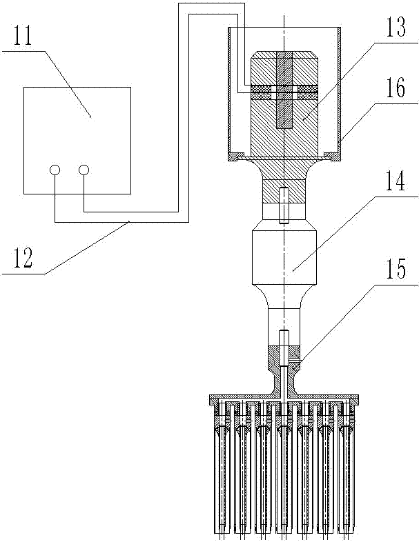
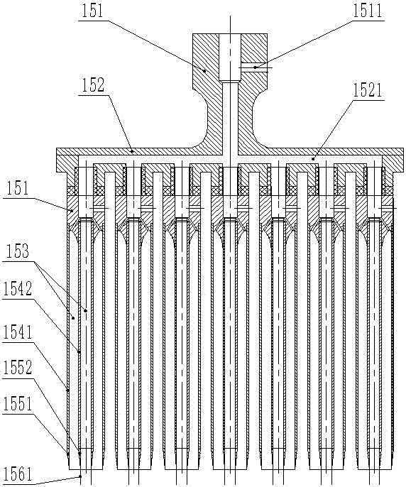
[0041] Such as figure 2 As shown, the multi-tube cutter 15 includes a connecting head 151 connected to the horn 14, a pipe body mounting plate 152 connected to the connecting head 151, and an internal cavity 153 is set on the pipe body mounting plate 152. The inner tube body 1542 and the outer tube body 1541, the inner cutting edge 1552, the outer cutting edge 1551, the first positioning pin 1561 and the second positioning pin 1562.

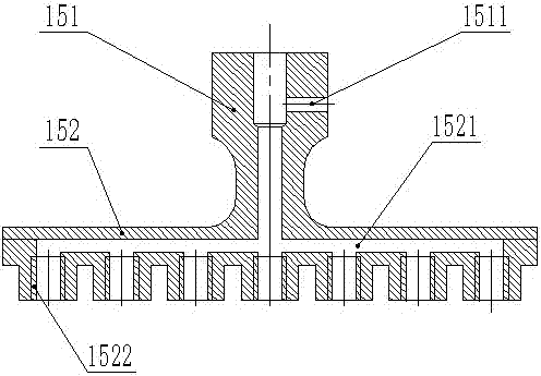
[0042] Such as image 3 As shown, the tube body installation plate 152 is integrally formed with the connector 151, the connector 151 is provided with a channel 1511, the tube body installation plate 152 is provided with an air distribution channel 1521, and one end of the channel 1511 is connected to the external The air compressor (not shown in the figure) is connected, and the other end is connected with the main head of the air distribution channel 1521, such as figure 2 As shown, each branch of the branch air channel 1521 communicates wi...

Embodiment 2

[0053] The difference from Embodiment 1 is that the tube body mounting plate 152 also includes a cover 1523 for the internally threaded hole 1522 . It is used to close the internally threaded hole 1522 that is not connected to the pipe body 154 .

[0054] For example, when the diameter of the pre-processed cylindrical hollow strip body 20 is relatively large, such as Figure 8 As shown, the external thread head 1533 of the pipe body 154 matches the internal thread hole 1522, and the cavity 153 matches the size of the pre-processed hole.

[0055] Since the outer diameter of the tube becomes larger, the tube body 154 cannot be sequentially arranged on the tube body mounting plate 152 , and the unused internal threaded hole 1522 is closed by the cover 1523 .

[0056] Using the processing process described in Embodiment 1, the processing of multiple cylindrical hollow strip blanks 20 can be realized.


PUM


Abstract

The invention particularly relates to a high-frequency vibration sponge array strip taking device and application. The device comprises an ultrasonic generator, an ultrasonic transducer connected with the ultrasonic generator through a wire, at least one stage of amplitude variation rod connected with the ultrasonic transducer and a multi-pipe cutter connected with the amplitude variation rod; the multi-pipe cutter is connected with the connected amplitude variation rod through threads, and comprises a connector connected with the amplitude variation rod, a pipe body placing plate connected with the connector, a plurality of pipe bodies which are arranged on the pipe body placing plate and internally comprise cavities and a cutting edge; and one end of each pipe body is detachably connected with the pipe body placing plate, and the other end of each pipe body is connected with the cutting edge. According to the technical scheme, strips can be easily taken out from a sponge in a high-frequency vibration manner, through design of the pipe body placing plate, simultaneous multi-hole forming work is achieved, the detachable connection manner is achieved, the use range can be greatly expanded through pipe body replacement, the production efficiency can be obviously improved, and the device is simple in structure.

Description

technical field [0001] The invention belongs to the sponge processing technology, and in particular relates to a strip-taking device of a high-frequency vibration sponge array, which is mainly used for processing the elastic body layer on the transfer roller in a printing copier. Background technique [0002] In daily life or industrial products, there are many cases where chipping processing is required on elastic materials such as artificial sponge, foam rubber, etc., but the above materials are easily deformed under slight pressure or torsion and tend to resist movement through compression or deformation. cutting or drilling action. [0003] The transfer roller of a printer or copier generally includes a metal mandrel and an elastomer layer sleeved outside the metal mandrel. The elastomer layer is usually the above-mentioned elastic material. In order to set the inner mandrel, holes need to be opened on the elastic material. . The transfer roller is the core component o...

Claims


Application Information

Patent Timeline
Patent Type & Authority Patents(China)
IPC IPC(8): B26D7/08B26D7/18B26D1/06
CPCB26D1/0006B26D1/06B26D7/086B26D7/1854B26D2001/006
Inventor 殷振周庆荣李艳钱蜜徐帖吴雷朱占军仝旭荣佳诚顾鸣伟
Owner SUZHOU UNIV OF SCI & TECH
Why Eureka
Try Eureka