Eureka AIR delivers breakthrough ideas for toughest innovation challenges, trusted by R&D personnel around the world.

Deceleration method of deceleration strip

A deceleration belt and speed technology, applied in the field of deceleration belt deceleration, can solve the problems of multiple springs, reduce the vibration of low-speed vehicles, slow rebound and reset of the deceleration belt, etc., meet the requirements of reducing stiffness, increasing magnetic field strength, and increasing service life Effect

Active Publication Date: 2016-06-15
泰州市海通资产管理有限公司
View PDF6 Cites 2 Cited by
  • Summary
  • Abstract
  • Description
  • Claims
  • Application Information

AI Technical Summary

Problems solved by technology

For example, the main purpose of the noise reduction hydraulic deceleration belt is to reduce the noise pollution generated when the vehicle passes the deceleration belt. In this design, there are many devices and the requirements for the spring are too high, and the deceleration belt rebounds and resets slowly; the visual deceleration belt mainly uses visual factors to achieve the deceleration effect; but the requirements for the environment are too high and the applicability is not strong
At the same time, the existing deceleration belts do not have the ability to distinguish the speed of driving vehicles, and cannot reduce the vibration of low-speed vehicles while maintaining punitive vibrations for high-speed vehicles.

Method used


Image

  • Deceleration method of deceleration strip
  • Deceleration method of deceleration strip
  • Deceleration method of deceleration strip

Examples


Embodiment Construction

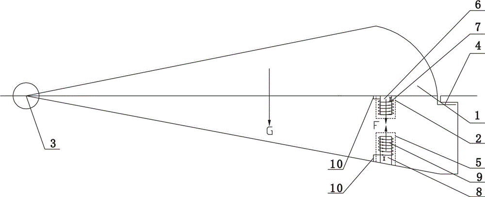
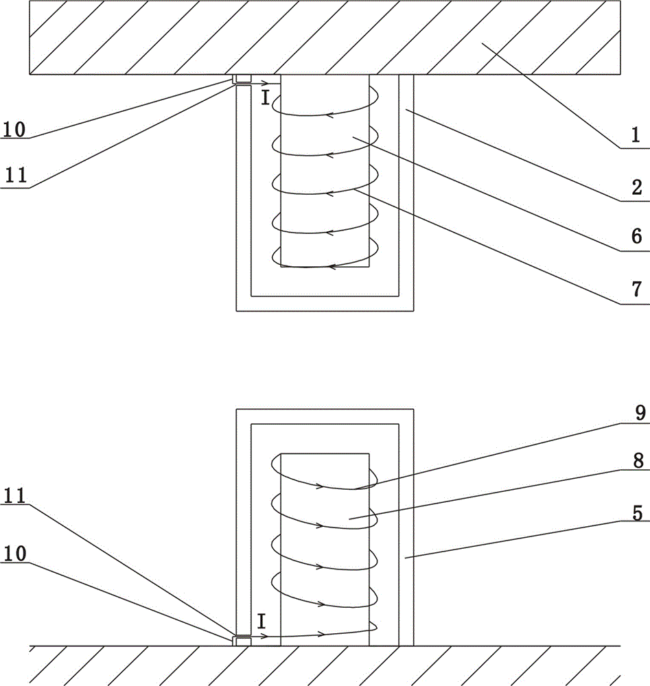
[0021] Such as figure 1 , figure 2 As shown, a deceleration method with a deceleration belt includes a deceleration panel 1, one end of the deceleration panel 1 is connected to a rotating shaft 3 fixed on the ground, the other end of the deceleration panel 1 is connected to the ground through a hook 4, and a first Metal box 2, the first metal box 2 is provided with a first DC electromagnet. Correspondingly, a second metal box 5 is fixed in the ground below the first metal box 2 , and a second DC electromagnet is arranged in the second metal box 5 . The first DC electromagnet is opposite to the second DC electromagnet with the same pole. The first DC electromagnet includes a first iron core 6 on which a first coil 7 is wound; the second DC electromagnet includes a second iron core 8 on which a second coil 9 is wound.

[0022] Both the first metal box 2 and the second metal box 5 are provided with side tunnels.

[0023] The cross-section of the deceleration panel 1 is in th...


PUM


Abstract

The invention provides a deceleration method of a deceleration strip. The deceleration strip comprises a deceleration panel. One end of the deceleration panel is connected with a rotary shaft fixed to the ground, and the other end of the deceleration panel is connected with the ground through a hook. A first metal box is fixedly installed under the deceleration panel. A first direct-current electromagnet is arranged in the first metal box. A second metal box is correspondingly arranged below the first metal box and located underground. A second direct-current electromagnet is arranged in the second metal box. The identical electrodes of the first direct-current electromagnet and the second direct-current electromagnet face each other. According to the deceleration method of the deceleration strip, the purpose of deceleration is achieved by means of the magnetic repulsive force F generated by the direct-current electromagnets; meanwhile, the blocking force of the deceleration strip can be adjusted and controlled by distinguishing the vehicle speed so that the deceleration strip can be adapted to different traffic environments.

Description

technical field [0001] The invention relates to a deceleration belt, in particular to a deceleration method of the deceleration belt. Background technique [0002] Judging from the use effect of speed bumps in recent years, speed bumps are a double-edged sword. Speed ​​bumps can effectively improve road traffic safety conditions, on the contrary, they may have little effect or even become artificial roadblocks on the road. Most of the current speed bumps make the road surface arched to achieve the purpose of vehicle deceleration. However, when the vehicle passes the speed bump, there will be violent vibration without exception, and the feeling of discomfort and insecurity will arise spontaneously. [0003] At present, a variety of new speed bumps have appeared in China, such as: noise reduction hydraulic speed bumps, visual speed bumps, etc., but most of these speed bumps can only solve some one-sided problems, and at the same time have many defects. For example, the main ...

Claims


Application Information

Patent Timeline
Patent Type & Authority Applications(China)
IPC IPC(8): E01F9/529
Inventor 刘杰佘剑波陈光富张梦宇夏骏徐玉柱王月
Owner 泰州市海通资产管理有限公司
Why Eureka
Eureka Blog
Learn More