door lock

A door lock and lock pin technology, which is applied in the field of electrical door locks with emergency release devices, can solve the problems of unfavorable door lock accurate control, lock pin position delay, slipping, etc., to avoid manual unlock failure and solve transmission delay , the effect of convenient operation

Inactive Publication Date: 2019-03-01
ILLINOIS TOOL WORKS INC
View PDF5 Cites 0 Cited by
  • Summary
  • Abstract
  • Description
  • Claims
  • Application Information

AI Technical Summary

Problems solved by technology

[0003] The current door locks are all driven by electric motors through the drive mechanism to drive the lock pin to extend and retract to close and open the door lock, but the drive mechanism converts the rotational motion of the motor into the linear motion of the lock pin. During the motion transmission process, there will be gear slippage or The slipping between the transmission wheels leads to a delay in the position of the lock pin, which is not conducive to the accurate control of the door lock; in addition, when the electrical appliances suddenly lose power, etc., an emergency unlocking device is required to open the door lock urgently

Method used


Image

  • door lock
  • door lock
  • door lock

Examples


Embodiment Construction

[0039] Various embodiments of the invention will be described below with reference to the accompanying drawings which form a part of this specification. It should be understood that although directional terms such as "front", "rear", "upper", "lower", "left", "right", "perpendicular", or "parallel" etc. are used in the present invention Various example structural parts and elements of the invention are described, but these terms are used herein for convenience of description only, based on the example orientations shown in the drawings. Since the disclosed embodiments may be arranged in different orientations, these directional terms are used for illustration only and should not be regarded as limiting. In the following drawings, the same reference numerals are used for the same components, and similar reference numerals are used for similar components to avoid repeated description.

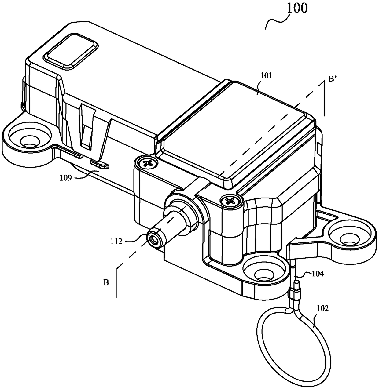
[0040] figure 1 It is a schematic diagram of the three-dimensional structure of the door lo...


PUM


Abstract

The invention discloses a door lock which is used for locking an electrical equipment door. The door lock comprises a driving gear (305), a lock pin driving wheel (210), a lock pin (110), a spring element (510) and the like. According to the door lock, the driving gear (305) drives the lock pin driving wheel (210) to rotate synchronously; and when rotating in the second direction under the exogenic action, the lock pin driving wheel (210) overcomes the friction of the spring element (510) on the inner top of the lock pin driving wheel (210) and the inner bottom of the driving gear (305), so that the lock pin driving wheel (210) does not drive the driving gear (305), and accordingly the lock pin driving wheel (210) rotates on the driving gear (305) in a sliding mode.

Description

technical field [0001] The invention relates to an electrical door lock, in particular to an electrical door lock with an emergency release device. Background technique [0002] The current electrical equipment all need to install a door lock mechanism with higher security. Taking a washing machine as an example, it is necessary to install a fixed door lock mechanism to lock its top plate to prevent the large drum type washing machine from rotating at a high speed during operation (or still rotating at a high speed due to inertia after it stops running), possibly damage to the human body. [0003] The current door locks are all electric motors through the drive mechanism to drive the lock pin to extend and retract to close and open the door lock, but the drive mechanism converts the rotational motion of the motor into the linear motion of the lock pin. During the movement transmission process, there will be gear slippage or The slip between the transmission wheels causes t...

Claims


Application Information

Patent Timeline
Patent Type & Authority Patents(China)
IPC IPC(8): E05B47/00E05B15/00E05B65/00
Inventor 汪洋
Owner ILLINOIS TOOL WORKS INC
Why Eureka
Try Eureka