
Turbine with deep peak regulation function and thermodynamic system

A thermal system and steam turbine technology, which is applied in the direction of steam engine devices, steam generation, mechanical equipment, etc., can solve the problems of waste of clean energy, inability to be fully utilized, and loss of peak-shaving ability of heating units.

Active Publication Date: 2016-06-15
山西漳电科学技术研究院(有限公司) +2
View PDF9 Cites 21 Cited by
  • Summary
  • Abstract
  • Description
  • Claims
  • Application Information

AI Technical Summary

Problems solved by technology

[0002] At present, thermal power units account for about 70% of my country's power generation capacity. The power generation pattern dominated by thermal power will not change for a long time in the future. Thermal power is the main force of power generation and is also the main means of peak regulation in the grid. For thermal power units specially used for peak regulation, all thermal power units basically participate in peak regulation. During the heating period, many heating units lose their peak regulation capability. The unit needs to participate in peak regulation, and its high efficiency cannot be fully utilized. On the other hand, due to the insufficient peak regulation capacity of the power grid, a large amount of wind power has to be abandoned frequently, clean energy is wasted, and investment cannot be effectively returned

Method used


Image

  • Turbine with deep peak regulation function and thermodynamic system
  • Turbine with deep peak regulation function and thermodynamic system
  • Turbine with deep peak regulation function and thermodynamic system

Examples


Embodiment 1

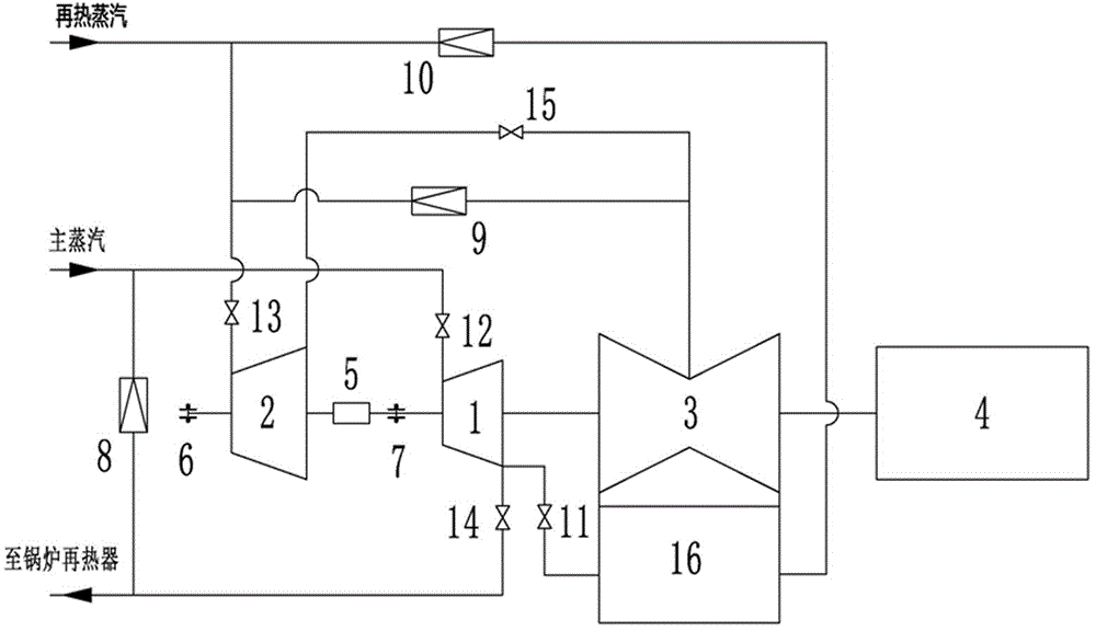
[0013] Embodiment 1: A steam turbine and thermal system with deep peak regulation function, including high-pressure cylinder 1, medium-pressure cylinder 2, low-pressure cylinder 3, generator 4, synchronous automatic clutch 5, first thrust bearing 6, and second thrust bearing 7. Medium pressure bypass valve 9, high pressure exhaust steam ventilation valve 11, high pressure steam inlet regulating valve 12, medium pressure steam inlet regulating valve 13, high pressure exhaust steam check valve 14, medium pressure exhaust steam butterfly valve 15, steam exhaust device 16 , in the shaft system of the unit, the medium pressure cylinder 2, high pressure cylinder 1, low pressure cylinder 3, and generator 4 are connected in sequence, and a synchronous automatic clutch 5 is set between the medium pressure cylinder 2 and the high pressure cylinder 1, and the steam inlet of the medium pressure cylinder 2 The first thrust bearing 6 is set on the side, and the second thrust bearing 7 is set...

Embodiment 2

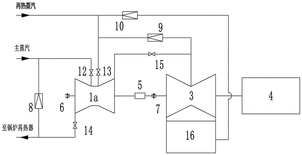
[0015] Embodiment 2: A steam turbine and thermal system with deep peak regulation function, including high and medium pressure cylinder 1a, low pressure cylinder 3, generator 4, synchronous automatic clutch 5, first thrust bearing 6, second thrust bearing 7, high pressure inlet Steam regulating valve 12, medium pressure steam inlet regulating valve 13, high pressure exhaust steam check valve 14, medium pressure exhaust steam butterfly valve 15, exhaust device 16, in the unit shaft system, high and medium pressure cylinder 1a, low pressure cylinder 3, generator 4 connected in sequence, a synchronous automatic clutch 5 is set between the high and medium pressure cylinder 1a and the low pressure cylinder 3, the first thrust bearing 6 is set on the high pressure exhaust side of the high and medium pressure cylinder 1a, and the side of the low pressure cylinder 3 close to the synchronous automatic clutch 5 is set The second thrust bearing 7, the main steam pipeline is connected to t...

Embodiment 3

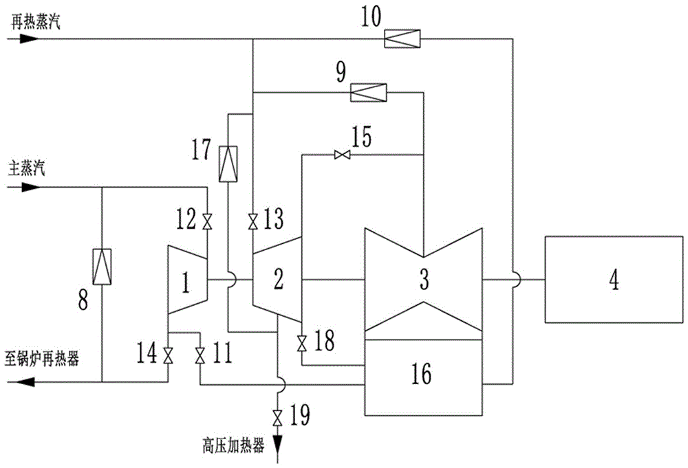
[0017] Embodiment 3: A steam turbine and thermal system with deep peak regulation function, including high-pressure cylinder 1, medium-pressure cylinder 2, low-pressure cylinder 3, generator 4, high-pressure exhaust steam ventilation valve 11, high-pressure steam inlet regulating valve 12, medium Pressure inlet steam regulating valve 13, high pressure exhaust steam check valve 14, medium pressure exhaust steam butterfly valve 15, steam exhaust device 16, reheat steam desuperheating and pressure reducing device 17, medium pressure exhaust steam ventilation valve 18, steam extraction check valve 19. In the shaft system of the unit, the high-pressure cylinder 1, the medium-pressure cylinder 2, the low-pressure cylinder 3, and the generator 4 are connected in sequence, and the main steam pipeline is connected to the steam inlet end of the high-pressure cylinder 1 through the high-pressure steam inlet regulating valve 12, and the high-pressure cylinder 1 The exhaust end of the cylin...


PUM


Abstract

The invention relates to the field of thermal power generation, in particular to a turbine with a deep peak regulation function and a thermodynamic system. The turbine comprises an intermediate-pressure cylinder, a synchronous automatic clutch, a high-pressure cylinder, a low-pressure cylinder, an intermediate-pressure by-pass valve and the like, wherein the intermediate-pressure cylinder, the synchronous automatic clutch, the high-pressure cylinder and the low-pressure cylinder are connected with one another through a coupler and connected with a power generator through the output end of a low-pressure rotor. During deep peak regulation of a unit, a high-pressure steam inlet regulation valve and an intermediate-pressure steam inlet regulation valve are closed, the intermediate-pressure cylinder is cut off through the synchronous automatic clutch, the high-pressure cylinder is vacuumized through a vent valve, a high-pressure by-pass valve and the intermediate-pressure by-pass valve of the unit are opened, steam from a boiler directly enters the low-pressure cylinder for acting, the unit is maintained to operate with low power output, and the purpose of deep peak regulation of the unit is achieved.

Description

technical field [0001] The invention relates to the field of thermal power generation, in particular to a steam turbine and a thermal system with a deep peak regulation function. Background technique [0002] At present, thermal power units account for about 70% of my country's power generation capacity. The power generation pattern dominated by thermal power will not change for a long time in the future. Thermal power is the main force of power generation and is also the main means of peak regulation in the grid. For thermal power units specially used for peak regulation, all thermal power units basically participate in peak regulation. During the heating period, many heating units lose their peak regulation capability. The unit needs to participate in peak regulation, and its high efficiency cannot be fully utilized. On the other hand, due to the insufficient peak regulation capacity of the power grid, a large amount of wind power has to be abandoned frequently, clean energy...

Claims


Application Information

Patent Timeline
IPC IPC(8): F01K11/02F01K13/02F22B33/18
CPCF01K11/02F01K13/02F22B33/18
Inventor 杨德荣宁志刚李王斌杨文王灵梅孟恩隆魏君波朱振荣
Owner 山西漳电科学技术研究院(有限公司)
Learn More