
A washing machine

A technology of washing machine and annular chamber, which is applied in the field of washing machine and can solve the problems of consumption, energy waste, and excess power

Active Publication Date: 2016-06-22
HISENSE(SHANDONG)REFRIGERATOR CO LTD
View PDF10 Cites 8 Cited by
  • Summary
  • Abstract
  • Description
  • Claims
  • Application Information

AI Technical Summary

Problems solved by technology

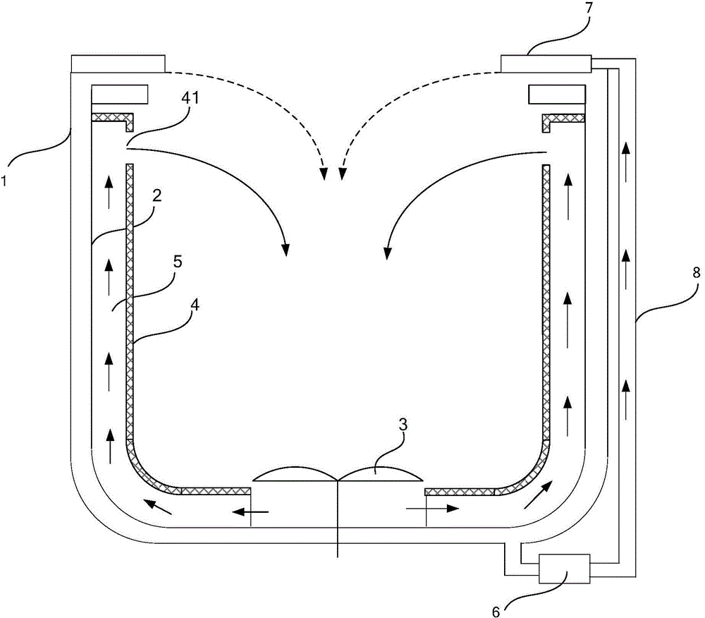
In the existing products, in order to achieve the continuous spraying effect, the external force of the circulating water pump is usually used to pump the water to the upper part for spraying, such as image 3 As shown, the washing machine also includes a circulating water pump 6, a spraying device 7, and an external conduit 8 communicating with the circulating water pump 6 and the spraying device 7, but this kind of spraying mechanism needs to be provided with an additional circulating water pump, which consumes too much electricity and causes a huge waste of energy

Method used


Image

  • A washing machine
  • A washing machine
  • A washing machine

Examples


Embodiment Construction

[0037] The following will clearly and completely describe the technical solutions in the embodiments of the present invention with reference to the accompanying drawings in the embodiments of the present invention. Obviously, the described embodiments are only some, not all, embodiments of the present invention. Based on the embodiments of the present invention, all other embodiments obtained by persons of ordinary skill in the art without making creative efforts belong to the protection scope of the present invention.

[0038] In describing the present invention, it is to be understood that the terms "center", "upper", "lower", "front", "rear", "left", "right", "vertical", "horizontal", The orientations or positional relationships indicated by "top", "bottom", "inner", "outer", etc. are based on the orientations or positional relationships shown in the drawings, and are only for the convenience of describing the present invention and simplifying the description, rather than in...


PUM


Abstract

The embodiment of the invention provides a washing machine and relates to the technical field of washing machines. A spray effect can be achieved without a circulating water pump. The washing machine comprises an inner bucket, and a pulsator arranged at the bottom of the inner bucket. The upper portion of the wall of the inner bucket is provided with a first annular cavity. The inner bucket of the washing machine is provided with a spray channel which makes the first annular cavity communicate with the bottom of the inner bucket. The first annular cavity comprises a water outlet and a water inlet. The water inlet is in butt joint with one end of the spray channel and the other end of the spray channel is located at the bottom of the inner bucket. The embodiment is used for washing machine manufacture.

Description

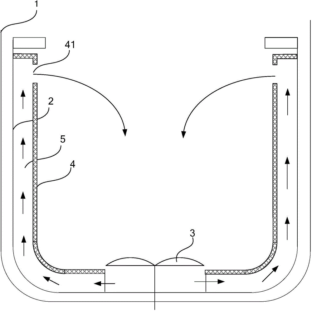
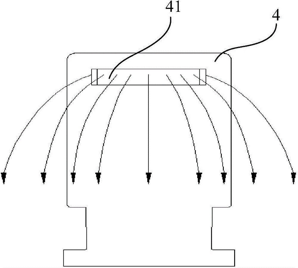
technical field [0001] The invention relates to the technical field of washing machines, in particular to a washing machine. Background technique [0002] In order to strengthen the movement of the clothes in the water of the washing machine and prevent the clothes from being entangled, a waterfall mechanism is usually arranged in the inner tub of the washing machine. in figure 1 The structure of a washing machine in the prior art is shown in , comprising: an outer tub 1, an inner tub 2, a pulsator 3, and a waterfall plate 4, wherein the waterfall plate 4 and the inner wall of the inner tub 2 form a waterfall channel 5, said The lower end of the waterfall channel 5 is positioned at the bottom of the inner barrel, and the waterfall plate is provided with a water outlet 41 at the position corresponding to the middle and upper part of the inner barrel (refer to figure 2 As shown), when the pulsator rotates, the centrifugal force makes the water flow into the waterfall channe...

Claims


Application Information

Patent Timeline
Patent Type & Authority Applications(China)
IPC IPC(8): D06F39/08
Inventor 董彦磊许运九刘振华张旭涛
Owner HISENSE(SHANDONG)REFRIGERATOR CO LTD
Learn More