A metallographic specimen polishing fixture

A technology for polishing fixtures and test pieces, which is applied in the direction of grinding workpiece holders and preparation of test samples. It can solve the problems of easy heating and darkening of the sample surface, low production efficiency, and low safety, and achieve the metallographic process of polishing. Simple and convenient, simple structure, flexible use effect

Active Publication Date: 2018-01-02
FENGYANG L S NET FORMING CO LTD
View PDF9 Cites 0 Cited by
  • Summary
  • Abstract
  • Description
  • Claims
  • Application Information

AI Technical Summary

Problems solved by technology

Most of the domestic products are manually operated fixtures, most of which are very complicated to install and operate, and the product design cost is high, which cannot really achieve the simple and convenient purpose of designing such products. The production efficiency is low, the safety is low, and the cooling conditions are poor. As a result, the metallographic polishing process is time-consuming and labor-intensive, and the poor cooling conditions make the surface of the sample easy to heat up and become dark, reducing the polishing quality; domestic products also have semi-automatic and fully automatic products, mainly to solve the problem of fixing samples of different shapes and sizes , but there are still problems such as low efficiency and low polishing precision
In the patent publications of CN202330127U and CN202433236U, the proposed clamp structure is cumbersome, the clamp wall thickness is complicated, and the operation is complicated. In the patent publication of CN105150094A, a clamp is disclosed, which is simple in structure and beneficial to clamping, but lacks Cool or fix the fixture and other safety protection devices

Method used


Image

  • A metallographic specimen polishing fixture
  • A metallographic specimen polishing fixture
  • A metallographic specimen polishing fixture

Examples


Embodiment Construction

[0022] The present invention will be further described below in conjunction with the accompanying drawings.

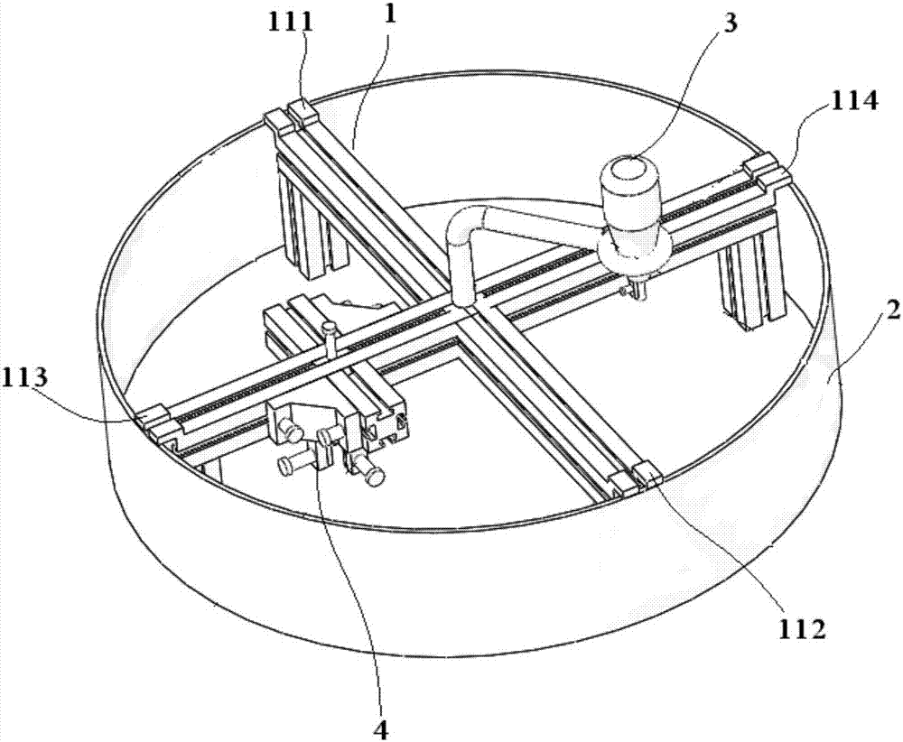
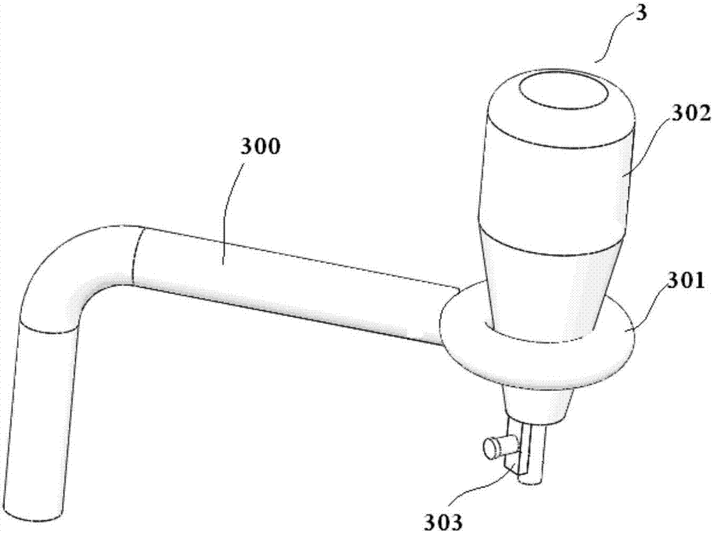
[0023] Such as figure 1 As shown, the metallographic specimen polishing fixture provided by the present invention includes a cross-shaped fixed bracket module 1 and a protective cover module 2 connected to the cross-shaped fixed bracket module 1, a dripping module 3 and a sample holding module 4 , the protective cover module 2 has added a safety protection function, which can prevent the sample from flying out at high speed and being damaged due to the failure of the fixture. The added cooling drip device 3 with automatic adjustable speed and volume can improve the polishing accuracy while ensuring the polishing accuracy. The degree of automation of the grinding and polishing process improves the polishing accuracy.

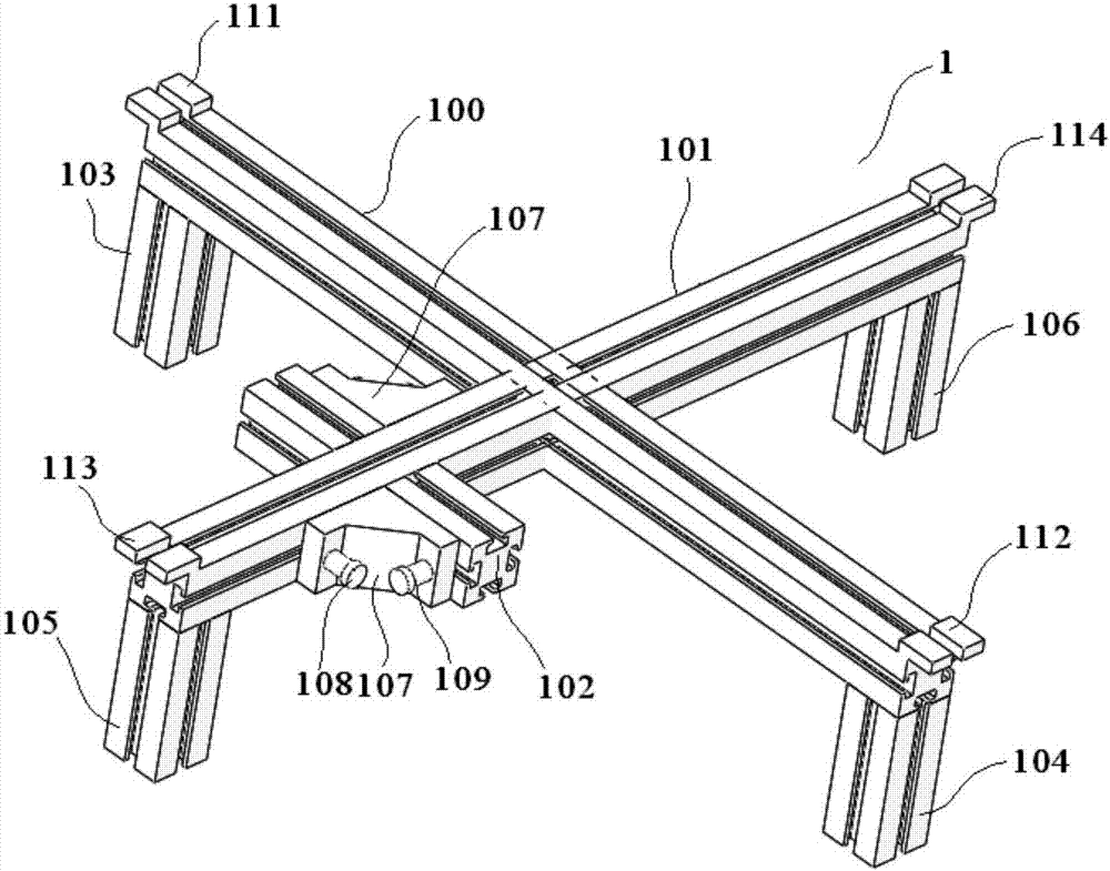
[0024] Such as figure 2 As shown, the cross-shaped fixed support module 1 includes a first main support 100 and a second main support 101 that are per...


PUM


Abstract

The invention discloses a metallographical test piece polishing clamp. The metallographical test piece polishing clamp comprises a cross-shaped fixing support module, a protection cover module, a liquid dropping module and a test sample clamping module, wherein the protection cover module, the liquid dropping module and the test sample clamping module are connected with the cross-shaped fixing support module. The metallographical test piece polishing clamp is simple in product structure and convenient to operate, the clamp and devices for fixing the clamp are arranged, the design of a clamping screw enables the clamp to be used more flexibly, the clamping condition of the clamp can be adjusted in time according to the shape sizes and the stress conditions of test samples, and the polishing accuracy is adjusted. According to the product, the multiple test samples can be polished at the same time, the manufacturing efficiency of metallographical samples is improved, other resources do not need to be consumed, and therefore the metallographical polishing process is easy, rapid and convenient. A guide rail support is adopted, and the position of the test sample clamping device can be freely adjusted in the guide rail direction, so that any-position movement of the test samples on a polishing disc is achieved, and the requirement for polishing is met.

Description

technical field [0001] The invention relates to a jig, in particular to a metallographic specimen polishing jig. Background technique [0002] At present, there have been relevant researches on metallographic polishing fixtures at home and abroad. There are many domestic fixture products with different structures. They can be classified into horizontal type, lifting type and full-motion type according to the motion trajectory. Most of the domestic products are manually operated fixtures, most of which are very complicated to install and operate, and the product design cost is high, which cannot really achieve the simple and convenient purpose of designing such products. The production efficiency is low, the safety is low, and the cooling conditions are poor. As a result, the metallographic polishing process is time-consuming and labor-intensive, and the poor cooling conditions make the surface of the sample easy to heat up and become dark, reducing the polishing quality; dom...

Claims


Application Information

Patent Timeline
Patent Type & Authority Patents(China)
IPC IPC(8): B24B41/06G01N1/32
CPCB24B41/06G01N1/32
Inventor 周健刘庚杨建凯禹霖吴佳英
Owner FENGYANG L S NET FORMING CO LTD
Why Eureka
Try Eureka