A heating component in an ICP etching device and a method for arranging the heating component

A technology for heating components and devices, applied in induction heating devices, induction heating and other directions, can solve problems such as cracking, achieve the effect of improving capacity and uniformity, and reducing the influence of induction magnetic fields

Active Publication Date: 2018-10-30
ADVANCED MICRO FAB EQUIP INC CHINA
View PDF4 Cites 0 Cited by
  • Summary
  • Abstract
  • Description
  • Claims
  • Application Information

AI Technical Summary

Problems solved by technology

The intensity of the electromagnetic field generated by the induction coil 2 needs to be set arbitrarily according to the needs of the plasma treatment process, but the temperature distribution on the ceramic radio frequency window 103 does need to be relatively stable and cannot be changed rapidly, otherwise it will crack due to frequent thermal expansion and contraction

Method used


Image

  • A heating component in an ICP etching device and a method for arranging the heating component
  • A heating component in an ICP etching device and a method for arranging the heating component
  • A heating component in an ICP etching device and a method for arranging the heating component

Examples


Embodiment Construction

[0041] based on the following Figure 3 ~ Figure 5 , specifically explain the preferred embodiment of the present invention.

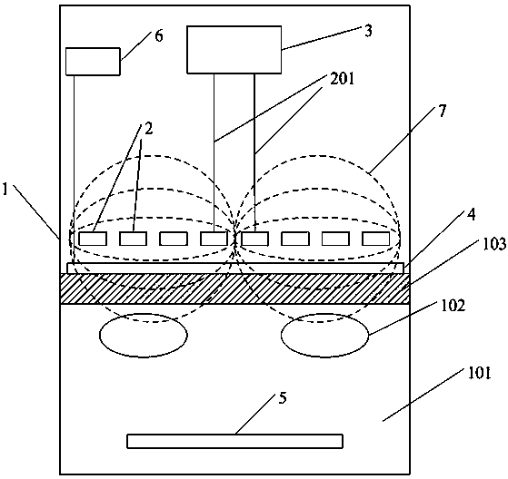
[0042] Such as image 3 Shown, described ICP etching device 1 comprises:

[0043] An induction coil 2, the two ends of the induction coil 2 are connected to the radio frequency source 3 through a lead wire 201, and under the excitation of the radio frequency source 3, the induction coil 2 generates an induced magnetic field;

[0044] A vacuum chamber 101, the reaction gas in the vacuum chamber 101 generates a plasma 102 under the action of the induced magnetic field generated by the induction coil 2, and etches the semiconductor substrate 5;

[0045] A ceramic radio frequency window 103, which isolates the induction coil 2 from the vacuum cavity 101, the ceramic radio frequency window 103 is flat or dome-shaped;

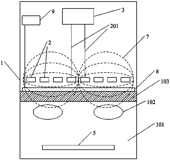
[0046] The heating assembly 8 includes a resistance wire 801 and a power source 9 connected to both ends of the resistance wire. The resi...


PUM


Abstract

A heating component in an ICP etching device and a heating component setting method are provided. According to the invention, a complete resistance wire component is arranged in a layered manner, resistance wire parts of each layer form a resistance wire layer, a resistance wire connection part connects the resistance wire parts in adjacent resistance wire layers, an insulation material layer is arranged between every two adjacent resistance wire layers, and the resistance wire parts in all the resistance wire layers are of the same shape and overlap in position in an up-down manner so the area of the closed loop infinitely approaches zero. According to the invention, generation of inductive electromotive force in the closed loop formed by the heating component is avoided, the influence on the inductive magnetic field formed by an induction coil is reduced greatly, and the capability and uniformity of heating are improved.

Description

technical field [0001] The invention relates to the field of semiconductor manufacturing, in particular to a heating assembly in an ICP etching device and a method for arranging the heating assembly. Background technique [0002] Such as figure 1 Shown is a schematic diagram of the structure of the ICP etching device 1, the ICP etching device includes a planar spiral induction coil 2, the two ends of the induction coil 2 are connected to the radio frequency source 3 through the lead wire 201, and the induction coil 2 is excited by the radio frequency source 3 , generating an induced magnetic field (magnetic field lines 7 such as figure 1 shown by the dotted line). The ceramic radio frequency window 103 isolates the planar spiral induction coil 2 from the vacuum chamber 101. The vacuum chamber 101 is filled with reaction gas. Under the action of the electromagnetic field, the gas discharge generates plasma 102 to etch the semiconductor substrate 5. Heating assembly 4 compr...

Claims


Application Information

Patent Timeline
Patent Type & Authority Patents(China)
IPC IPC(8): H05B6/10
Inventor 万磊黄智林庞晓贝
Owner ADVANCED MICRO FAB EQUIP INC CHINA
Why Eureka
Try Eureka