Dead zone wiping device for equipment parts

A technology of parts and dead zones, which is applied in the field of dead zone wiping devices, can solve problems such as wiping dead zones, and achieve thorough wiping and good cleaning effects

Inactive Publication Date: 2016-07-06
HAIAN GASOLINEEUM SCI RES INSTR
View PDF6 Cites 0 Cited by
  • Summary
  • Abstract
  • Description
  • Claims
  • Application Information

AI Technical Summary

Problems solved by technology

Usually, a towel is used to wipe the dirty parts, but the dead area cannot be wiped, so a new technical solution needs to be provided to solve the above technical problems

Method used


Image

  • Dead zone wiping device for equipment parts

Examples


Embodiment Construction

[0007] The present invention will be further described below in conjunction with the accompanying drawings and specific embodiments.

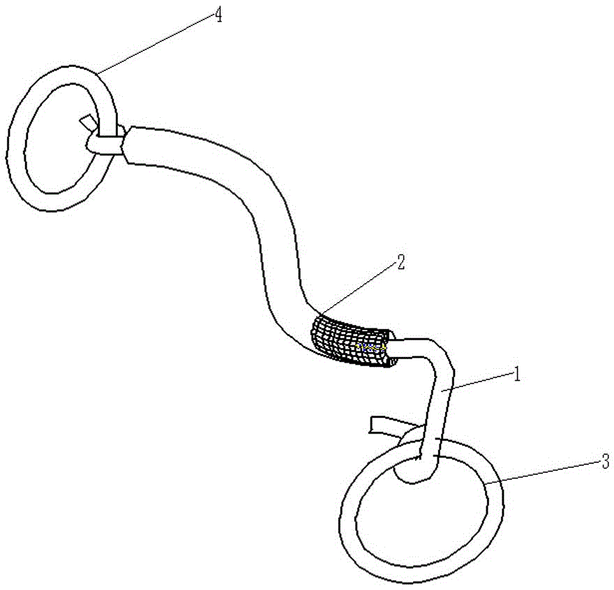
[0008] figure 1 Middle: nylon rope 1, wiping cotton cover 2, first pull ring 3, second pull ring 4.

[0009] The dead zone wiping device for equipment parts includes a nylon rope 1. The dead zone wiping device for equipment parts also includes a first pull ring 3 and a second pull ring 4. The rope body of the nylon rope 1 is fixedly connected with a wiping cotton sleeve 2 , the wiping cotton cover 2 covers the rope body of the nylon rope 1, one end of the nylon rope 1 is connected to the first pull ring 3, and the other end of the nylon rope 1 is connected to the second pull ring 4 . During use, one end of the nylon rope 1 is inserted through the gap between the parts and then pulled out, and then the two ends of the nylon rope 1 are respectively studded and fixedly connected to the first pull ring 3 and the second pull ring 4 . The operato...


PUM


Abstract

The invention relates to a dead zone wiping device for equipment parts. The device comprises a nylon rope and also comprises a first pull ring and a second pull ring, wherein the rope body of the nylon rope is fixedly connected with a wiping cotton sleeve; the wiping cotton sleeve covers the rope body of the nylon rope; one end of the nylon rope is connected with the first pull ring; and the other end of the nylon rope is connected with the second pull ring. The device disclosed by the invention has the beneficial effects that dead zones of the equipment parts can be completely wiped and the dirt cleaning effect is good.

Description

technical field [0001] The invention relates to auxiliary tools, in particular to a device for wiping dead areas of equipment parts. Background technique [0002] During the long-term use of mechanical equipment, the surface of its parts is prone to dirt, especially the accumulation of dirt on moving parts such as crankshafts will affect the operating performance of the machine. Therefore, it is necessary to remove dirt by wiping to realize the maintenance of mechanical equipment. Usually, a towel is used to wipe the dirty parts, but the dead zone cannot be wiped. Therefore, a new technical solution needs to be provided to solve the above technical problems. Contents of the invention [0003] The invention overcomes the disadvantages of the background technology and provides a device for wiping dead areas of equipment parts. The device can wipe the dead areas of equipment parts thoroughly and has good dirt cleaning effect. [0004] The present invention provides the foll...

Claims


Application Information

Patent Timeline
Patent Type & Authority Applications(China)
IPC IPC(8): B08B1/00
CPCB08B1/006
Inventor 金雪松王永明
Owner HAIAN GASOLINEEUM SCI RES INSTR
Why Eureka
Try Eureka