Supercharge Your Innovation With Domain-Expert AI Agents!

Rail guide device for machining

A technology of orbital guidance and machining, applied in the direction of mechanical equipment, linear motion bearings, bearings, etc., can solve the problem that it is difficult to avoid the entry of pollutants, and achieve the effect of smooth operation

Inactive Publication Date: 2016-07-06
黄国锦
View PDF6 Cites 2 Cited by
  • Summary
  • Abstract
  • Description
  • Claims
  • Application Information

AI Technical Summary

Problems solved by technology

However, due to the influence of the slider embedded in the recessed guide rail groove, the width of the guard strip is narrower than the width of the guide rail groove, so there is still a gap and it is difficult to prevent the entry of pollutants at all

Method used


Image

  • Rail guide device for machining
  • Rail guide device for machining
  • Rail guide device for machining

Examples


Embodiment Construction

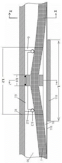
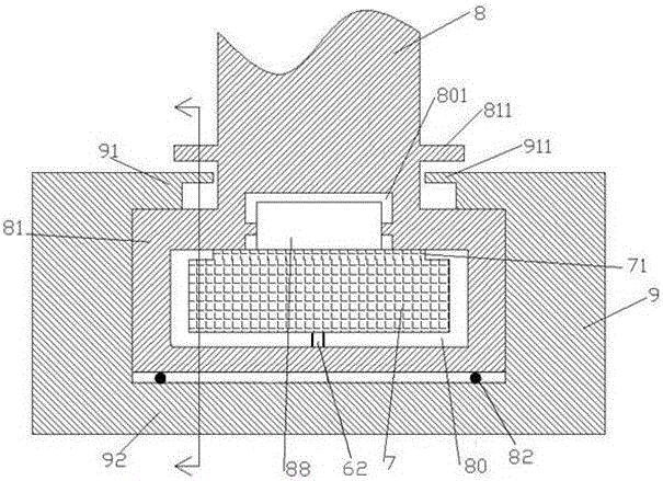
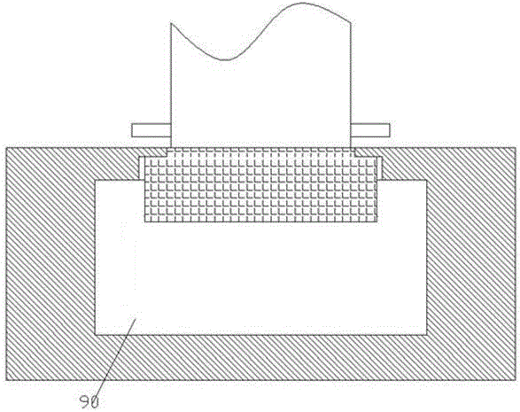
[0010] Combine below Figure 1-3 The present invention will be described in detail.

[0011] A rail guiding device for machining according to an embodiment, comprising a rail member 9 and a sliding member base 8 that is slidably fitted with the rail member 9 and fixedly connected with the sliding member. The rail member 9 includes an upper The side wall 91 and the bottom wall 92 thus define the housing of the guide rail sliding cavity 90 therebetween, and the sliding member base 8 has a sliding engagement seat 81 fitted in the guide rail sliding cavity 90 and is integrated with the sliding engagement seat 81 The connecting neck that is connected and protrudes upwards through the longitudinal groove of the guide rail in the upper side wall 91 is used to be fixedly connected with the sliding part. The bottom of the sliding joint seat 81 is equipped with a roller 82, and the roller 82 is used for To abut against the bottom wall 92, so that the sliding joint seat 81 can run smoot...


PUM


Abstract

The invention provides a rail guide device for machining. The rail guide device comprises a guide rail part, and a slide part base which is in sliding match with the guide rail part and is fixedly connected with a slide part, wherein the guide rail part comprises a shell body which is provided with an upper side wall and a bottom wall to limit a guide rail slide chamber between the upper side wall and the bottom wall; the slide part base is provided with a slide junction seat which is matched inside the guide rail slide chamber and a connection neck part which is integrally connected with the slide junction seat, passes through a guide rail longitudinal groove in the upper side wall and stretches out upwards to be fixedly connected with the slide part; rolling wheels are mounted at the bottom of the slide junction seat, and are used for abutting against the bottom wall; and a protection belt positioning flange is arranged on the upper side wall in an extending manner in the direction toward the guide rail longitudinal groove, longitudinally stretches into the guide rail longitudinal groove and is intersected with an elastic protection belt for sealing the guide rail slide chamber, so that limitation is realized.

Description

technical field [0001] The invention relates to the field of rail guides, in particular to a rail guide for machining. Background technique [0002] In machining technology, orbital guide is a commonly used guide method, which is used to guide the movement of sliding parts. The specific structure of the guide rail has a protruding type and a concave type. For the upward protruding guide rail, due to its structural shape, it is difficult to adapt to some occasions that require no protrusion. Inner concave guide rails are widely used in some occasions that require the compactness of the equipment and the flatness of the shape. However, due to its concave structure, this kind of concave guide rail is susceptible to the entry of external pollutants to cause the accumulation of pollutants, which especially has an impact on the precision of the guide device for precision motion. Moreover, it is inconvenient to maintain, which adversely affects the use and service life of the eq...

Claims


Application Information

Patent Timeline
Patent Type & Authority Applications(China)
IPC IPC(8): F16C29/02F16C29/08
CPCF16C29/02F16C29/084
Inventor 黄国锦
Owner 黄国锦
Features
  • R&D
  • Intellectual Property
  • Life Sciences
  • Materials
  • Tech Scout
  • Unparalleled Data Quality
  • Higher Quality Content
  • 60% Fewer Hallucinations
Learn More