A unified description method for the operating state of a safe and stable emergency control device

A safe, stable, emergency control technology, applied in the direction of circuit devices, electrical components, etc., can solve the problems of not directly uploading the throwing and withdrawing status, and achieve the effect of improving monitoring and management capabilities

Active Publication Date: 2018-06-05
NARI TECH CO LTD +4
View PDF3 Cites 0 Cited by
  • Summary
  • Abstract
  • Description
  • Claims
  • Application Information

AI Technical Summary

Problems solved by technology

[0007] However, at present, security and stability emergency control devices generally do not directly send their own throwing and withdrawing status

Method used


Image

  • A unified description method for the operating state of a safe and stable emergency control device
  • A unified description method for the operating state of a safe and stable emergency control device
  • A unified description method for the operating state of a safe and stable emergency control device

Examples


Embodiment 1

[0057] The safe and stable emergency control device D is the control device, and formula (1) is embodied as formula (2);

[0058] R(D)=! S(BLOCK)&&S(ZGNYB) (2)

[0059] in,! Indicates the logical "not" operation, and && indicates the logical "and" operation.

[0060] As long as the device locking abnormal state and the key platen state of the control device D all meet the following two conditions, the control device D is considered to be in the commissioning state:

[0061] A) There is no device locking abnormality, that is, S(BLOCK)=0;

[0062] B) The total function of the platen input, that is, S(ZGNYB)=1.

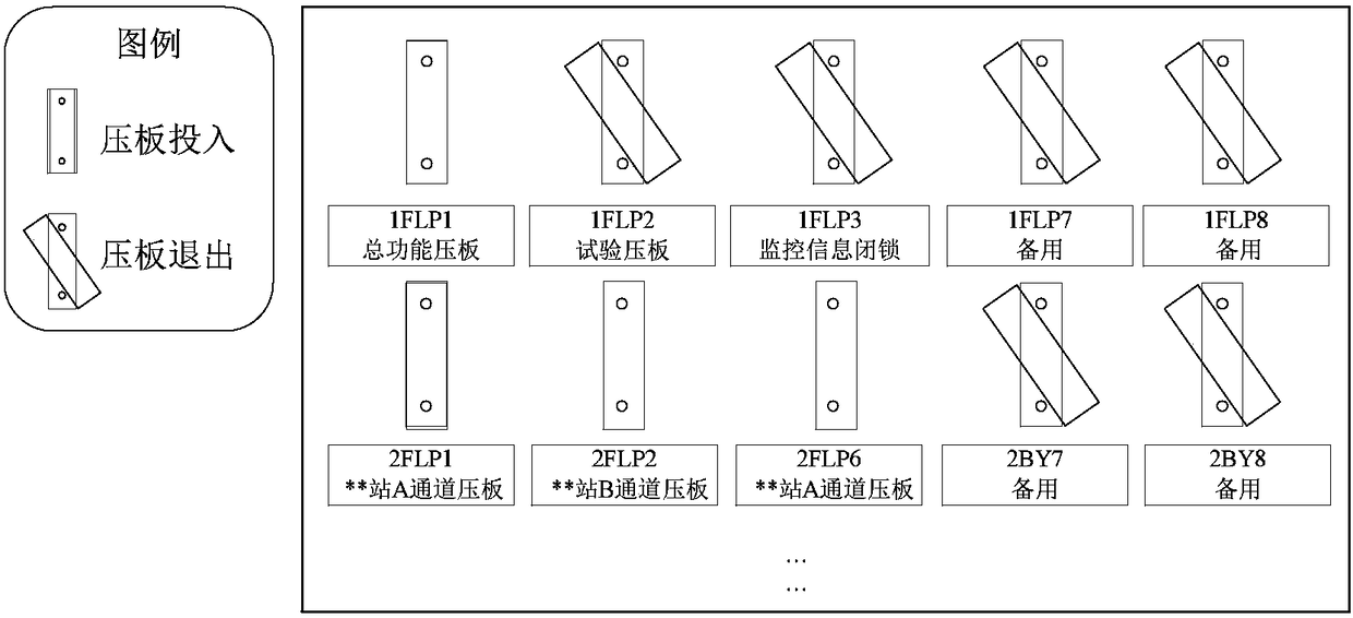
[0063] figure 1 Assuming that there is no device lock-up in the middle control device D, condition A is met, and the input of the total function pressing plate 1FLP1 meets condition B, so the pressing plate state of the control device D is in figure 1 state, the operating state of the control device D is determined to be in the commissioning state.

[0064] figu...

Embodiment 2

[0066] When the safety and stability emergency control device D is the executive device, formula (1) is embodied as formula (3):

[0067]

[0068]

[0069] Among them, ∨ represents the collective logic "OR" operation, ∧ represents the collective logic "AND" operation; u is the global unique index of the uth trip outlet pressure plate in the safety and stability emergency control device D in the safety and stability emergency control device D, S( CKYB u ) is the u-th trip outlet pressure plate CKYB in the safety and stability emergency control device D u dropout status.

[0070]

[0071] In fact, it indicates whether the device is in the input state, and the result is 1, indicating that the device is in the input state, and 0, indicating that it is in other states other than the input state. It means that as long as the key platen status of the actuator D satisfies the following three conditions, the actuator D is considered to be in the commissioning state:

[0072...


PUM


Abstract

The invention discloses a uniform description method for operating states of safe and stable emergency control devices, and belongs to the technical field of dispatch operation monitoring of a power system. According to the method, uniform description is carried out on the operating states of the safe and stable emergency control devices , which are determined by blocking abnormal states of the devices and deblocking and blocking states of a total functional pressure plate, switching-allowable pressure plates and outlet pressure plates; and respective operating states of different safe and stable emergency control devices can be described by different forms of formulas. The method can achieve online automatic identification of the operating states of the safe and stable emergency control devices at a dispatch end, and provides a technical support for a dispatching operator for timely and accurately monitoring the real-time operating states of the safe and stable emergency control devices.

Description

technical field [0001] The invention belongs to the technical field of power system dispatching operation monitoring, and in particular the invention relates to a method for uniformly describing the operating state of a safe and stable emergency control device. Background technique [0002] As the function of the inter-regional interconnection grid changes from mutual support between systems to large-capacity inter-regional power transmission, the use of safety and stability control devices can not only ensure the safe and stable operation of the power grid, but also play an important role in improving the transmission capacity of inter-regional interconnection grids. Therefore, it is very important for the dispatcher to grasp the operation status of the safety and stability control device in time. [0003] The normal operating status of the safety and stability control device can generally be divided into three types, namely, operation, signal input, and exit; and these ope...

Claims


Application Information

Patent Timeline
Patent Type & Authority Patents(China)
IPC IPC(8): H02J13/00
CPCH02J13/00001
Inventor 王阳王胜明徐泰山才洪全顾健辉沈凤杰边二曼邵伟徐洪涛孙才峰
Owner NARI TECH CO LTD
Why Eureka
Try Eureka