A lock screw fixture

A technology for locking screws and jigs, which is applied in the direction of manufacturing tools, metal processing, and metal processing equipment. It can solve the problems of easily scratching the appearance of products, difficulty in quickly locking screw holes, and screw or screw hole slipping, so as to improve the quality of screws. Lock payment efficiency, reduce defect rate, and avoid the effect of sliding teeth

Active Publication Date: 2017-09-12
昆山铭世特智能科技有限公司
View PDF7 Cites 0 Cited by
  • Summary
  • Abstract
  • Description
  • Claims
  • Application Information

AI Technical Summary

Problems solved by technology

However, due to the fixed position of the existing screw locking jig, it is easy to scratch the appearance of the product during the installation of the screw and cause the screw or screw hole to slip and it is difficult to quickly lock the position of the screw hole.

Method used


Image

  • A lock screw fixture
  • A lock screw fixture
  • A lock screw fixture

Examples


Embodiment Construction

[0019] The present invention will be further described below in combination with specific embodiments.

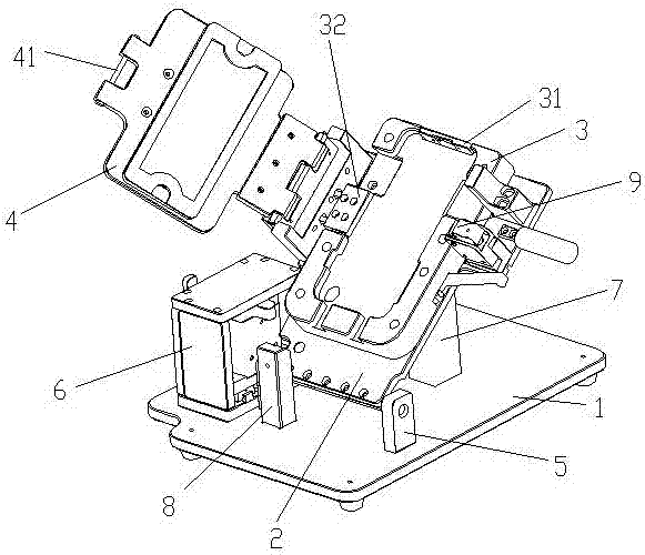
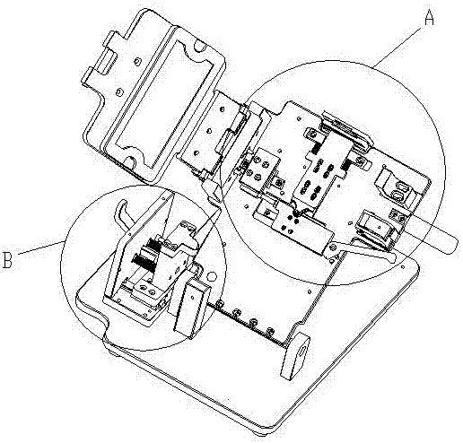
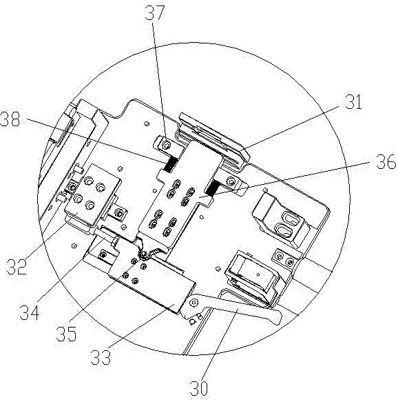
[0020] Such as Figure 1 to Figure 5 As shown, a locking screw fixture includes a base 1, on which a base 2 that can rotate relative to it is provided, on which a product fixing device 3 is arranged, and the upper end of the product fixing device 3 An upper fixing plate 31 is provided, and a screw guide sleeve 311 is arranged on the upper fixing plate 31. The base 1 is provided with a first support column 7 for supporting the base plate 2 and making it inclined and for supporting The base plate 2 is formed into a vertical second support column 8 .

[0021] When the substrate 2 is pressed against the first support column 7, the product fixing device 3 is in an inclined state, which is convenient for fixing the product therein. After the product is fixed, by rotating the substrate 2, the product fixing device 3 is driven to rotate to a vertical shape, Keep the axis of the s...


PUM


Abstract

The invention discloses a screw fastening jig which comprises a base.A base plate capable of rotating relative to the base is arranged on the base.A product fixing device is arranged on the base plate.An upper fixing plate is arranged at the upper end of the product fixing device, a screw guide sleeve is arranged on the upper fixing plate, and a first supporting column and a second supporting column are arranged on the base, wherein the first supporting column is used for supporting the base plate to make the base plate be in an inclined state, and the second supporting column is used for supporting the base plate to make the base plate be in a perpendicular state.A product is fixed when the product fixing device is in an inclined state, and then the product fixing device is rotated to make the axis of a screw hole and the horizontal plane be perpendicular and maintain the state; a product protection hood and the screw guide sleeve are adopted to prevent the surface of the product from being scratched in the screw fastening state, screw loose of a screw or the screw hole is avoided, the screw fastening efficiency is improved, and thus the defective rate is reduced.

Description

technical field [0001] The invention relates to a screw locking jig, which belongs to the technical field of electronic product processing equipment. Background technique [0002] In the assembly process of electronic products, screw locking is usually required, and the screw locking jig is usually required to cooperate in the process of installing screws. However, because the position of the existing screw locking jig is fixed, it is easy to scratch the appearance of the product during the installation of the screw and cause the screw or the screw hole to slip and it is difficult to quickly lock the position of the screw hole. Contents of the invention [0003] The technical problem to be solved by the present invention is to provide a screw locking jig. By adopting a product protective cover and a screw guide sleeve and keeping the axis of the screw hole perpendicular to the horizontal plane, it is possible to prevent the appearance of the product from being scratched wh...

Claims


Application Information

Patent Timeline
Patent Type & Authority Patents(China)
IPC IPC(8): B23P19/06
CPCB23P19/06
Inventor 张军
Owner 昆山铭世特智能科技有限公司
Why Eureka
Try Eureka