
Filature conveyer with positioning function

A transmission device and screw machine technology, which is applied in the direction of manufacturing tools, metal processing, metal processing equipment, etc., can solve the problems of only acting on one side or two sides of the shell, the labor intensity of the operator is high, and the production efficiency is affected. , to achieve the effect of improving lock payment efficiency, realizing positioning work, and reducing workload

Pending Publication Date: 2019-08-30
CHONGQING LINGLONG AUTOMATION EQUIP CO LTD
View PDF0 Cites 0 Cited by
  • Summary
  • Abstract
  • Description
  • Claims
  • Application Information

AI Technical Summary

Problems solved by technology

Most of the existing screw machines are equipped with a locking structure that can move in multiple dimensions to lock the shell. Since the locking surface will involve multiple sides of the shell, the locking structure can only be used to lock each side one by one. Lock payment, so it will inevitably affect production efficiency
In the locking process, in order to improve the accuracy of the locking, it is necessary to position the shell and then lock it. At present, the positioning of the shell and the loading and unloading work are mostly realized by manual transfer. In this way, not only the labor intensity of the operators is high, but also And the labor cost of production is also higher
In addition, after the existing positioning structure locates the shell, most of the locking structures can only act on one side or two sides of the shell. In this way, it is not suitable for screw machines that can lock multiple sides at the same time.

Method used


Image

  • Filature conveyer with positioning function
  • Filature conveyer with positioning function
  • Filature conveyer with positioning function

Examples


Embodiment 1

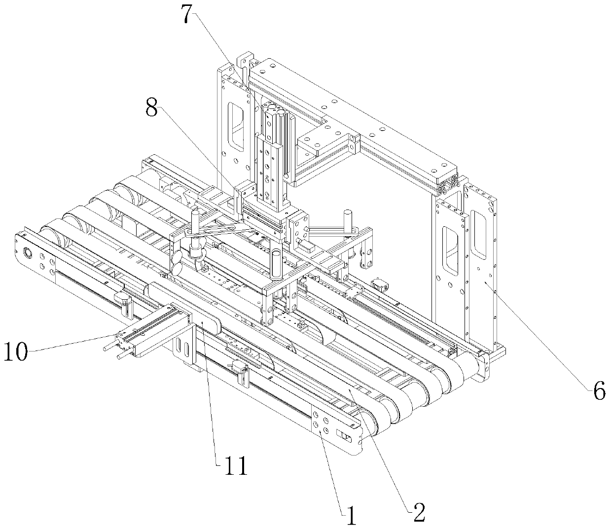
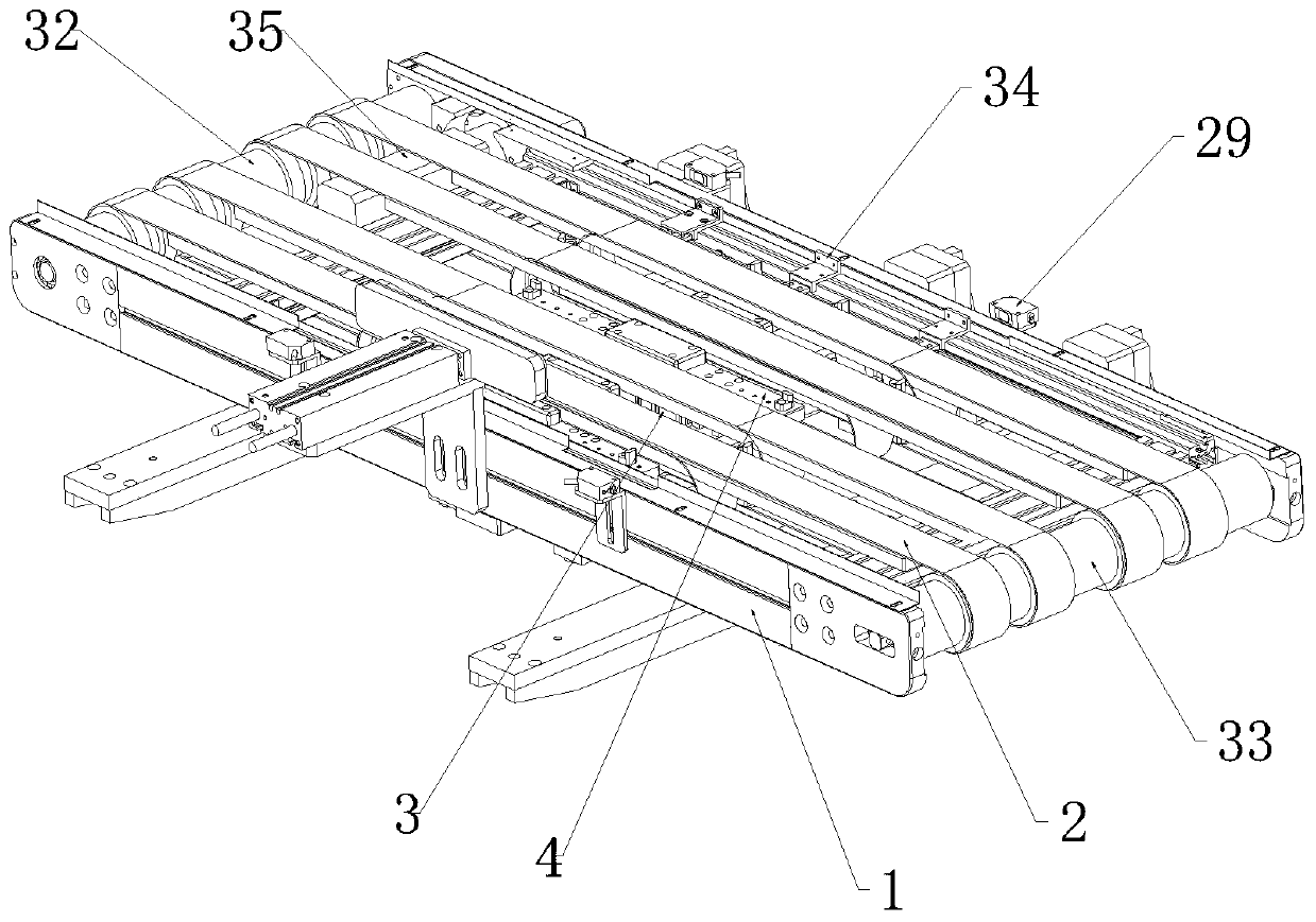
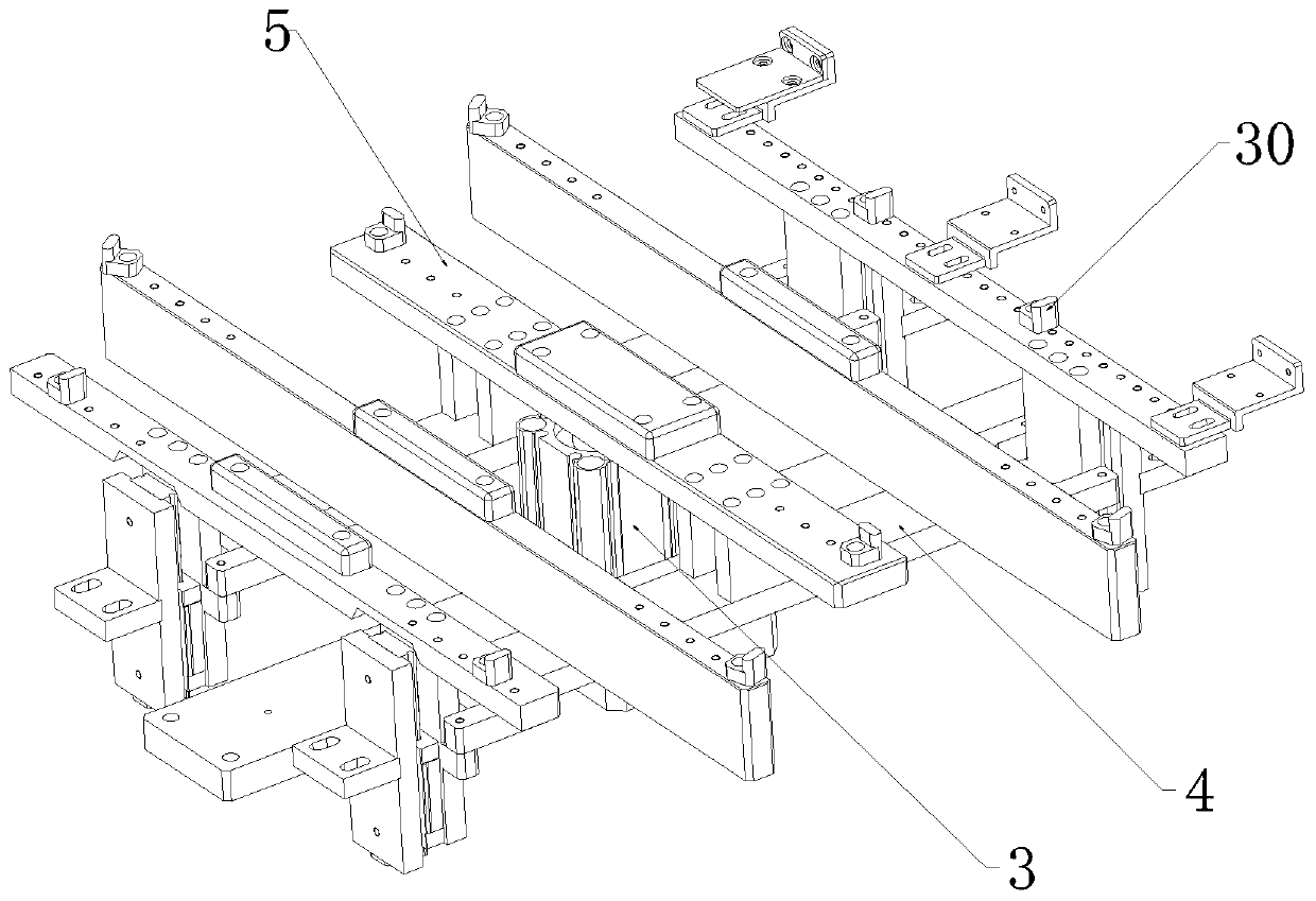
[0044] Such as Figure 1 to Figure 6 As shown, the screw machine transmission device with positioning function includes a transmission unit and a positioning unit;

[0045] The transmission unit includes a transmission frame 1; the transmission frame 1 is provided with at least two transmission belts 2 arranged at intervals, and the transmission frame 1 is equipped with a belt drive device for driving the transmission belt 2; the transmission frame 1 is equipped with a push rod drive In the device 3, the output end of the ejector rod driving device 3 is connected with the ejector rod connecting frame 4, and the ejector rod connecting frame 4 is provided with a ejector rod 5 which is staggered with the conveyor belt 2, and the ejector rod driving device 3 acts on the ejector rod 5 so that: The ejector rod 5 can move up and down relative to the conveyor belt 2;

[0046] The positioning unit includes a clamping support base 6, on which a pressing driving device 7 is installed, a...

Embodiment 2

[0049] This embodiment makes the following further limitations on the basis of Embodiment 1: a side pressure drive device 10 is installed on the transmission frame 1, and the output end of the side pressure drive device 10 is connected with a side pressure plate 11, and the side pressure drive device 10 functions Because of the side pressure plate 11, the side pressure plate 11 can move along the direction across the transmission frame 1;

[0050] Several ejector rods 5 are arranged on the ejector rod connecting frame 4, and the ejector rod 5 which is located farthest from the side pressure driving device 10 among the several ejector rods 5 is provided with at least two spacing protrusions. plate 34.

[0051] In this embodiment, the lateral pressure drive device 10 can be a sliding table cylinder, a double-axis cylinder, or the like. If the lateral pressure driving device 10 is located on the right side of the transmission frame 1 , then the limiting convex plate 34 is locate...

Embodiment 3

[0054] This embodiment makes the following further limitations on the basis of Embodiment 1: the elastic pressing member includes a pressing supporting column 12 and a movable cylinder 13 sleeved on the pressing supporting column 12, and the bottom end of the pressing supporting column 12 Connected with a limit head 14 that prevents the movable cylinder 13 from detaching from the pressing support column 12;

[0055] An elastic supporting member 15 is sleeved on the pressing support column 12 , and the elastic supporting member 15 acts on the movable cylinder 13 , so that the movable cylinder 13 is located at a low position and abuts against the limit head 14 .

[0056] In this embodiment, the elastic supporting member 15 may be a compression spring. Movable cylinder 13 can have the movable groove that top opening small inner cavity is big, and limit head 14 is positioned at movable groove and the outer diameter of limit head 14 is greater than the top opening width of movable ...


PUM


Abstract

The invention discloses a filature conveyer with a positioning function. The filature conveyer with the positioning function comprises a conveying unit and a positioning unit, wherein, the conveying unit comprises a conveying frame; a conveyer belt is arranged on the conveying frame in a driving manner, and a belt driving device used for driving the conveyer belt is mounted on the conveying frame;an ejector rob driving device is mounted on the conveying frame, and the output end of the ejector rob driving device is connected with an ejector rob connecting frame; and the positioning unit comprises a clamping support base, a down press driving device is mounted on the clamping support base, and the output end of the down press driving device is connected with a clamping driver. According tothe invention, the high stability of the positioning work of a notebook computer is realized, and that the notebook computer can receive the locking work from three sides can be ensured. Therefore, the workload of operators can be effectively reduced, and the production efficiency and production quality are also improved.

Description

technical field [0001] The invention relates to the technical field of notebook processing, in particular to a screw machine conveying device with a positioning function. Background technique [0002] The shell of the notebook computer is not only the most direct way to protect the body, but also an important factor affecting the cooling effect, weight and aesthetics of the notebook computer. Laptop casings are usually assembled using automatic screw machines for locking. Most of the existing screw machines are equipped with a locking structure that can move in multiple dimensions to lock the shell. Since the locking surface will involve multiple sides of the shell, the locking structure can only be used to lock each side one by one. Lock payment, so it will inevitably affect production efficiency. In the locking process, in order to improve the accuracy of the locking, it is necessary to position the shell and then lock it. At present, the positioning of the shell and the...

Claims


Application Information

Patent Timeline
Patent Type & Authority Applications(China)
IPC IPC(8): B23P19/06B23P19/00B23Q7/00
CPCB23P19/06B23P19/00B23Q7/00
Inventor 陈鑫鸿刘阳李国强
Owner CHONGQING LINGLONG AUTOMATION EQUIP CO LTD
Learn More