Garbage cracking furnace system

A cracking furnace and garbage technology, applied in incinerators, combustion methods, combustion types, etc., can solve the problems of polluted air, furnace wall corrosion, flue gas environmental pollution, etc., achieve uniform temperature balance in the furnace, improve work efficiency, avoid The effect of garbage accumulation

Inactive Publication Date: 2016-07-13
赵君华
View PDF8 Cites 7 Cited by
  • Summary
  • Abstract
  • Description
  • Claims
  • Application Information

AI Technical Summary

Problems solved by technology

Among them, the composting method and landfill method require a large amount of land resources, and are likely to cause secondary pollution to groundwater and soil
The simple incineration method will produce a large amount of harmful gases, and the incineration residues also need to be landfilled, causing too much pollution to the environment
The existing garbage cracking furnace directly cracks the garbage through high temperature, but the flue gas generated during the cracking process will still pollute the environment, even after being purified by various purification devices, there are still different degrees of harm
[0004] At the same time, the disadvantages of garbage cracking treatment are: the flue gas after garbage cracking contains a large amount of melted coke and high-temperature fly ash. These high-temperature substances will stick to the furnace wall or other pipe walls and become coke. Coking not only affects the movement of airflow in the furnace, but also corrodes the furnace wall, which is very difficult to clean
The garbage cracking furnace crushes the garbage outside the furnace, which causes the surrounding air to be polluted when the garbage is broken outside the furnace. At the same time, the crushing effect of the garbage once crushed is not thorough, which is likely to cause poor cracking effect and reduce the garbage quality. Working Efficiency of Cracking Furnace

Method used


Image

  • Garbage cracking furnace system
  • Garbage cracking furnace system
  • Garbage cracking furnace system

Examples


Embodiment Construction

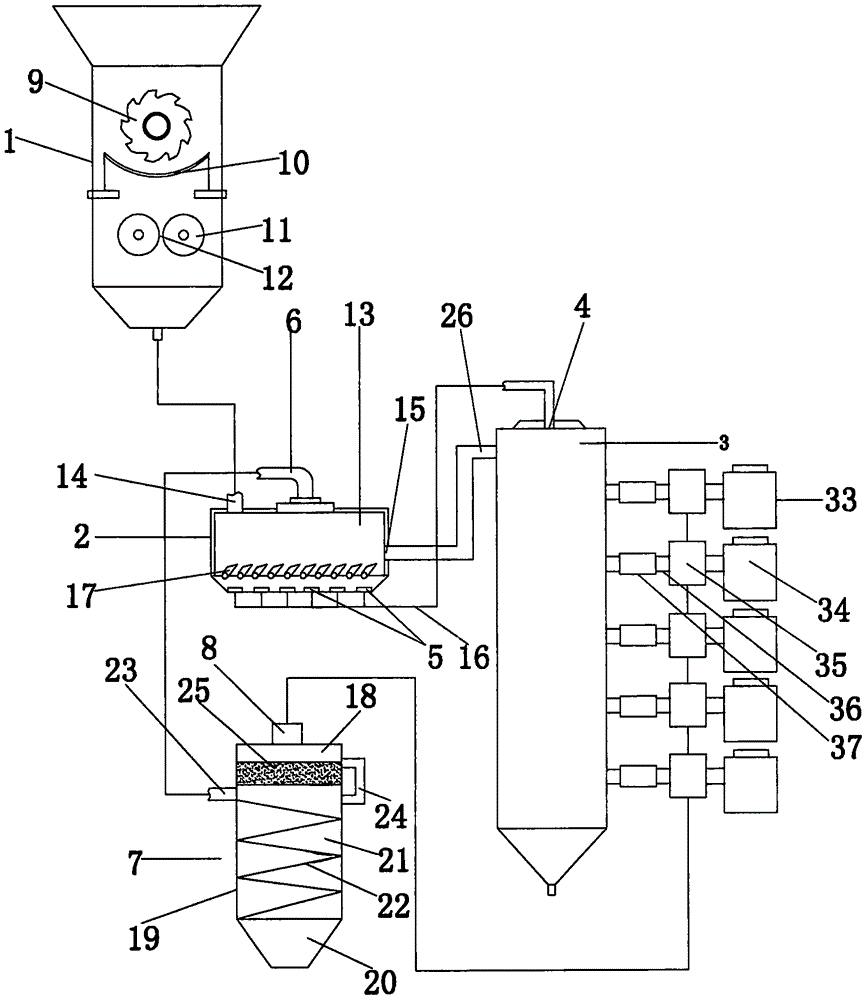
[0027] Below in conjunction with accompanying drawing, the present invention will be further described with specific embodiment: see Figure 1-5 ,

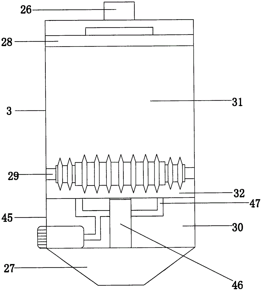
[0028] A garbage cracking furnace system, comprising a garbage crushing and dehydrating mechanism 1, a garbage pre-air-drying mechanism 2, and a garbage cracking furnace 3 connected in sequence, and the high-temperature waste gas outlet 4 of the garbage cracking furnace is connected to the hot air inlet of the garbage pre-air-drying mechanism through a pipeline 5. Then make the high-temperature waste gas pre-air-dry the garbage. The cold air outlet 6 of the garbage pre-air-drying mechanism is connected to the purification condenser 7, and the clean gas outlet 8 of the purification condenser is connected to the garbage cracking furnace so that the purified gas is returned to the garbage. Used in cracking furnace.

[0029] The specific structure of the described rubbish crushing and dewatering mechanism is: comprising a body, in wh...


PUM


Abstract

The invention provides a garbage cracking furnace system and belongs to the technical field of a garbage cracking furnace.The system solves the problems that an existing garbage cracking furnace causes environment pollution, and the cracking effect is not good.The garbage cracking furnace system comprises a garbage smashing and dehydrating mechanism, a garbage pre-airing mechanism and a garbage cracking furnace which are sequentially connected.A high-temperature waste gas outlet of the garbage cracking furnace is connected with a hot air inlet of the garbage pre-airing mechanism through a pipeline, and accordingly pre-airing treatment is conducted on garbage by means of high-temperature waste gas.A cold air outlet of the garbage pre-airing mechanism is connected to a purification condenser, and a purified air outlet of the purification condenser is connected to the garbage cracking furnace so that the purified air can return into the garbage cracking furnace for use.The system has the advantages of being capable of avoiding environment pollution, according with the concept of environment friendliness, improving work efficiency of the garbage cracking furnace, being high in carbon recycling efficiency and the like.

Description

technical field [0001] The invention belongs to the technical field of garbage cracking furnaces, in particular to a garbage cracking furnace system. Background technique [0002] With the continuous development of social economy and the gradual expansion of population size and urbanization, the generation of urban domestic waste continues to increase, and the pollution caused by domestic waste to the environment has become increasingly serious. The serious public hazard of domestic waste has become a serious public hazard facing the world today. A big and thorny issue. [0003] At present, there are three basic ways to deal with domestic waste: composting, landfilling, and incineration. Among them, the composting method and landfill method require a large amount of land resources, and are likely to cause secondary pollution to groundwater and soil. The simple incineration method will produce a large amount of harmful gases, and the residues of incineration also need to be...

Claims


Application Information

Patent Timeline
Patent Type & Authority Applications(China)
IPC IPC(8): F23G5/033F23G5/04F23G5/027F23G5/12F23G5/44
CPCF23G5/033F23G5/027F23G5/04F23G5/12F23G5/44F23G2201/10F23G2201/20F23G2201/30F23G2201/301F23G2201/80F23G2204/103F23G2206/10F23G2900/50204
Inventor 赵君华
Owner 赵君华
Why Eureka
Try Eureka