Mechanical movement conversion device

A technology of conversion device and mechanical movement, applied in the direction of transmission device, mechanical equipment, belt/chain/gear, etc., can solve the problem that the function of the equipment cannot be fully exerted, and achieve simple structure, wide application and high conversion efficiency. Effect

Inactive Publication Date: 2012-07-25
马明辉
View PDF3 Cites 9 Cited by
  • Summary
  • Abstract
  • Description
  • Claims
  • Application Information

AI Technical Summary

Problems solved by technology

[0002] At present, in mechanical motion mechanisms, such as air compressors and other machines, most of them convert the rotation of the motor into the linear reciprocating motion of the piston rod. However, in some machines, it is necessary to convert the linear reciprocating motion or the swinging rod into the rotation of the rotating shaft. For example, in tidal power generation, it is necessary to convert the swing of the connecting rod driven by the ups and downs of the ocean waves into the one-way rotation of the rotating shaft, so that the rotating shaft can drive the generator to output electric energy to the outside. However, there is no such type of structure in the known mechanical motion mechanism, making a large number of The function of the equipment can not be brought into full play

Method used


Image

  • Mechanical movement conversion device
  • Mechanical movement conversion device
  • Mechanical movement conversion device

Examples


Embodiment Construction

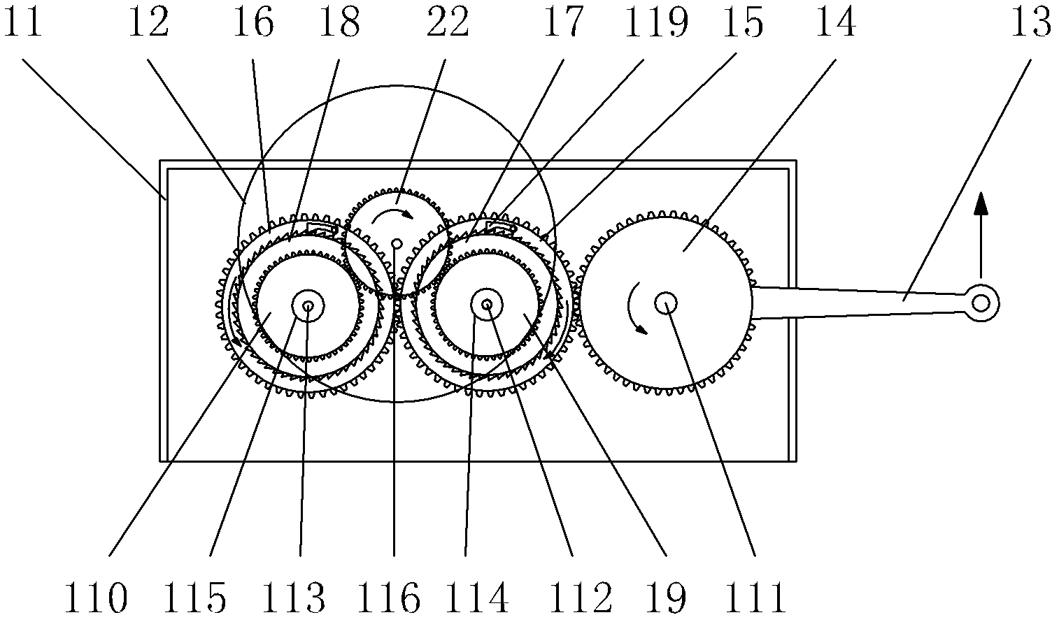
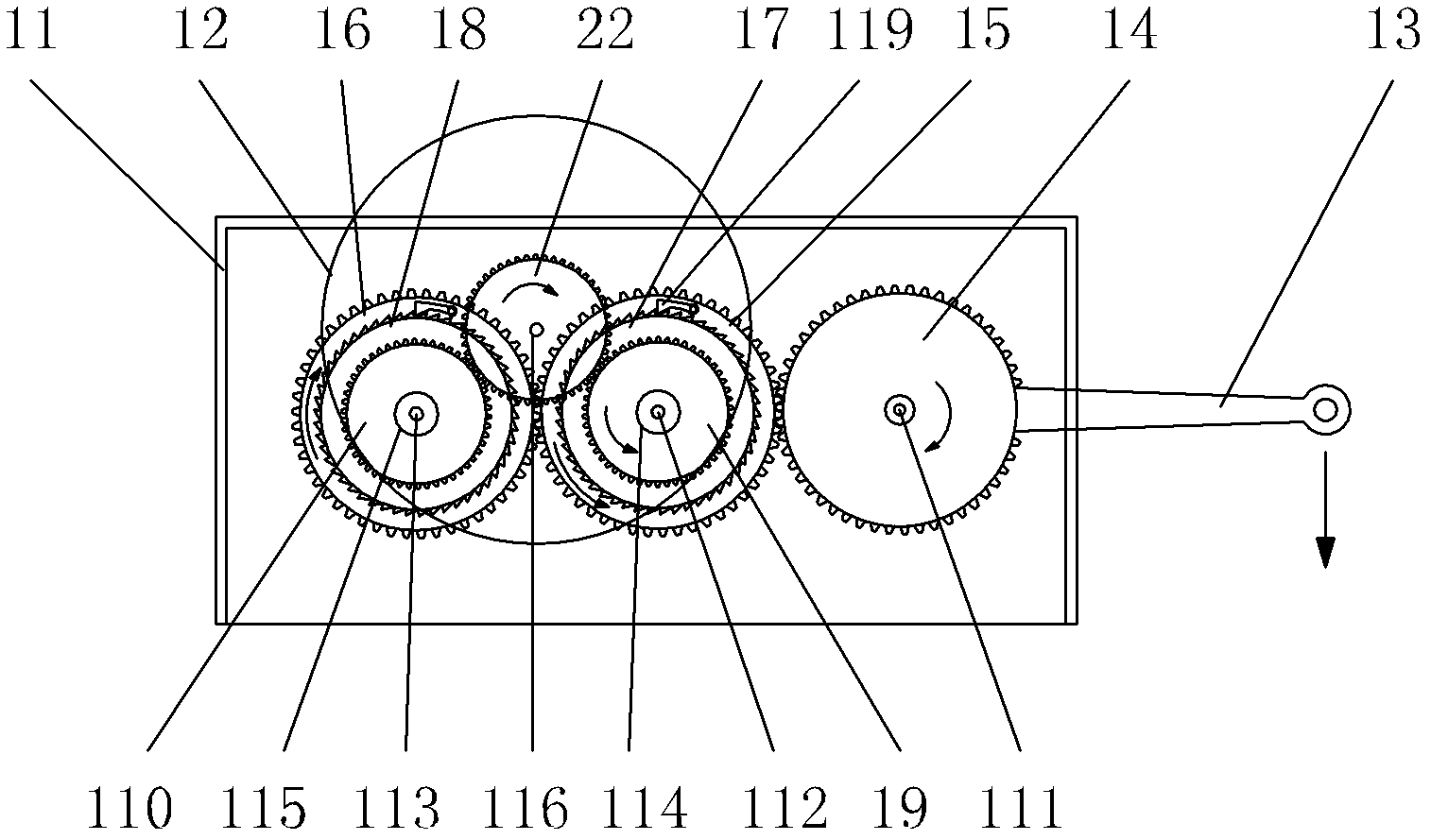
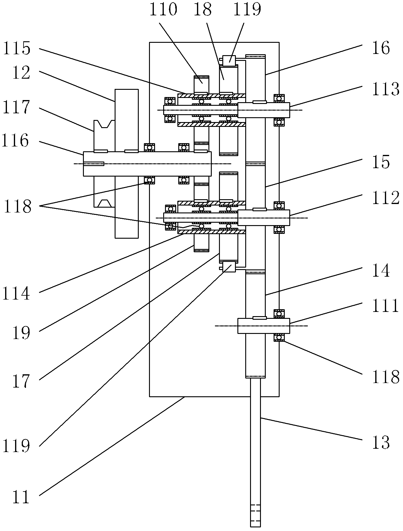
[0016] Below in conjunction with accompanying drawing, the present invention will be further described with specific embodiment, see Figure 1-4 :

[0017] A mechanical motion conversion device, in which three shafts 111, 2 112, and 113 are arranged parallel to each other in sequence in a box body 11, and three shafts 111, 2 112, and 3 113 are arranged respectively. The first-stage gears 14, 15, and 16 with equal pitch circles meshing with each other, the shaft one 111 or the first-stage gear 14 on the shaft one 111 are fixedly connected with the rocker arm 13, and the shaft two 112 and the shaft three 113 are respectively sleeved with hollow gears. The shafts 114, 115 and the hollow shafts 114, 115 are respectively fixedly connected with secondary gears 17, 18 whose pitch circle diameters are smaller than the pitch circle diameters of the primary gears 15, 16 and which rotate coaxially with the secondary gears 17, 18. For the three-stage gears 19, 110 whose indexing circle d...


PUM


Abstract

The invention belongs to the technical field of mechanical movement mechanism, and relates to a mechanical movement conversion device. A first shaft, a second shaft and a third shaft which are parallel to each other and sequentially disposed are arranged in a box, three primary gears which are meshed with each other are respectively arranged on the first shaft, the second shaft and the third shaft, a rocker arm is fixedly connected onto the first shaft or the primary gear on the first shaft, hollow shafts are respectively sleeved on the second shaft and the third shaft, secondary gears and tertiary gears are respectively fixedly connected onto the hollow shaft, each tertiary gear and the corresponding secondary gear rotate coaxially, a one-way rotary gear which is in meshed transmission with the two tertiary gears simultaneously is fixedly connected onto an output shaft disposed between the two tertiary gears, and pawls are respectively disposed on the primary gears which are fixedly connected onto the second shaft and the third shaft and drive the secondary gears to rotate when the primary gears rotate anticlockwise or clockwise. The mechanical movement conversion device has the advantages that conversion of movement modes is accurate and reliable, energy loss is low, conversion efficiency is high, and the mechanical movement conversion device is applicable to various mechanical equipment required conversion of reciprocating movement or oscillation into circumferential movement.

Description

technical field [0001] The invention belongs to the technical field of mechanical motion mechanisms, in particular to a mechanical motion conversion device. Background technique [0002] At present, in mechanical motion mechanisms, such as air compressors and other machines, most of them convert the rotation of the motor into the linear reciprocating motion of the piston rod. However, in some machines, it is necessary to convert the linear reciprocating motion or the swinging rod into the rotation of the rotating shaft. For example, in tidal power generation, it is necessary to convert the swing of the connecting rod driven by the ups and downs of the ocean waves into the one-way rotation of the rotating shaft, so that the rotating shaft can drive the generator to output electric energy to the outside. However, there is no such type of structure in the known mechanical motion mechanism, making a large number of The function of the device cannot be brought into full play. C...

Claims


Application Information

Patent Timeline
Patent Type & Authority Applications(China)
IPC IPC(8): F16H37/06
Inventor 马明辉
Owner 马明辉
Why Eureka
Try Eureka