Method and system for improving aerial survey accuracy of unmanned aerial vehicle and unmanned aerial vehicle

An unmanned aerial vehicle and high-precision technology, applied in the field of unmanned aerial vehicle remote sensing, can solve the problems of seldom application and high cost of POS technology products, and achieve the effect of reducing costs, widely used, and improving the accuracy of aerial surveying.

Inactive Publication Date: 2016-07-13
BEIJING MICROFLY ENG TECH CO LTD
View PDF4 Cites 1 Cited by
  • Summary
  • Abstract
  • Description
  • Claims
  • Application Information

AI Technical Summary

Problems solved by technology

However, high-precision POS technology products are expensive, and are currently mostly used in military investigations, national defense and security, and are rarely used in civilian drones, especially small and medium-sized drones.

Method used


Image

  • Method and system for improving aerial survey accuracy of unmanned aerial vehicle and unmanned aerial vehicle
  • Method and system for improving aerial survey accuracy of unmanned aerial vehicle and unmanned aerial vehicle
  • Method and system for improving aerial survey accuracy of unmanned aerial vehicle and unmanned aerial vehicle

Examples


Embodiment Construction

[0034] The following will clearly and completely describe the technical solutions in the embodiments of the present invention with reference to the accompanying drawings in the embodiments of the present invention. Obviously, the described embodiments are only some, not all, embodiments of the present invention. The components of the embodiments of the invention generally described and illustrated in the figures herein may be arranged and designed in a variety of different configurations. Accordingly, the following detailed description of the embodiments of the invention provided in the accompanying drawings is not intended to limit the scope of the claimed invention, but merely represents selected embodiments of the invention. Based on the embodiments of the present invention, all other embodiments obtained by those skilled in the art without making creative efforts belong to the protection scope of the present invention.

[0035] It should be noted that like numerals and let...


PUM


Abstract

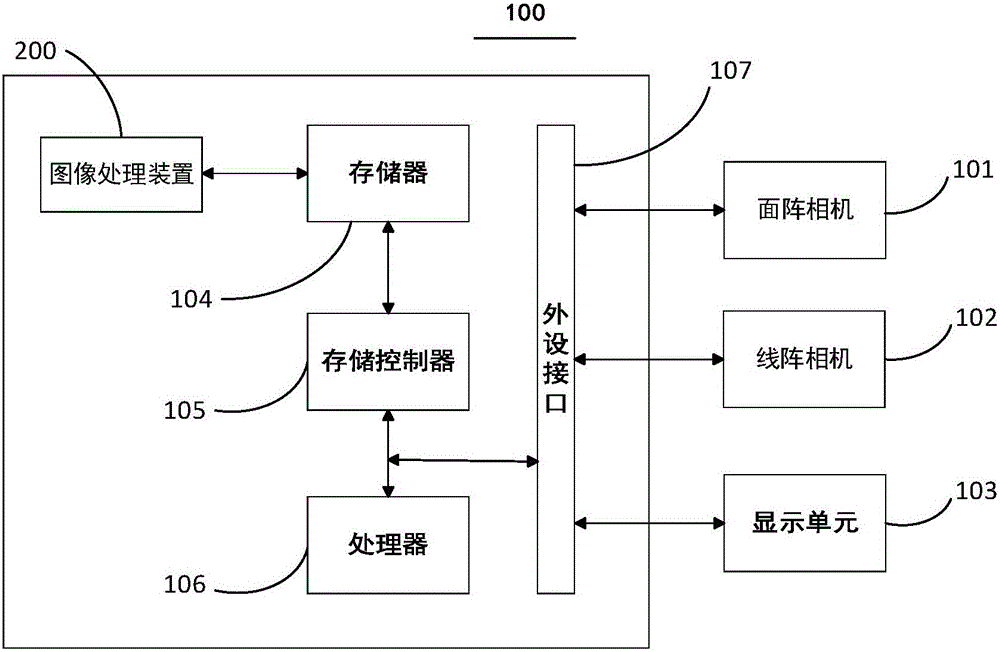
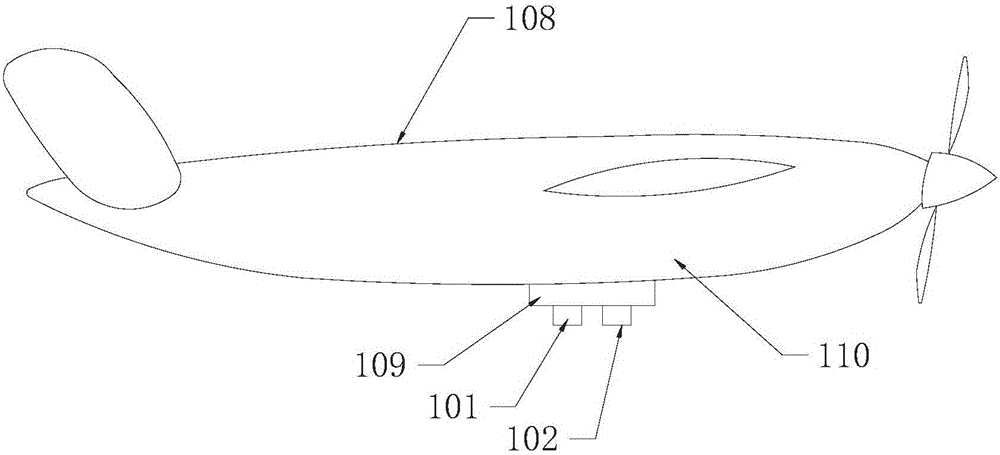
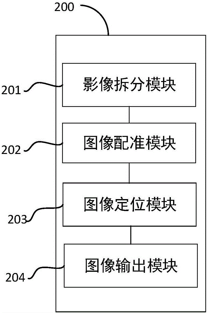
The invention provides a method and system for improving the aerial survey accuracy of an unmanned aerial vehicle and the unmanned aerial vehicle. An area array camera and a line array camera are arranged, shooting is carried out through the area array camera and the line array camera at the same time, frame images obtained through the area array camera and strip images obtained through the line array camera are registered, positioned and output again, and a high-resolution final image is obtained. The flying postures and position coordinate information of the unmanned aerial vehicle are obtained without a high-accuracy POS technology product, cost can be reduced, and the method and system and the unmanned aerial vehicle can be widely applied.

Description

technical field [0001] The present invention relates to the technical field of UAV remote sensing, in particular, to a method, system and UAV for improving the aerial survey accuracy of UAV. Background technique [0002] UAV remote sensing images are divided into area array cameras and line array cameras according to photographic cameras. At present, area array cameras are commonly used on drones, and only a small amount of line array cameras are used in the military field. In the industrial field, the solution of line scan camera plus scanning motion to acquire images is still widely used, especially when a large field of view and high image resolution are required, it cannot even be replaced by an area scan camera. However, due to the influence of scanning motion accuracy, its image is more specific than that of an area array camera. Therefore, in image recognition, it is not only necessary to make full use of the advantages of high resolution, but also to overcome the in...

Claims


Application Information

Patent Timeline
Patent Type & Authority Applications(China)
IPC IPC(8): H04N7/18G01C11/02G01C11/08G01C11/24G01C11/26
CPCG01C11/02G01C11/08G01C11/24G01C11/26G01C11/36H04N7/18
Inventor 薛强窦博雄鄂成文李晓虎叶方云
Owner BEIJING MICROFLY ENG TECH CO LTD
Why Eureka
Try Eureka