
Three-coordinate detecting instrument and supporting rack thereof

A technology for benches and mounting brackets, which is applied to workbenches, manufacturing tools, etc., and can solve the problems of low versatility

Inactive Publication Date: 2016-07-20
BEIQI FOTON MOTOR CO LTD
View PDF8 Cites 0 Cited by
  • Summary
  • Abstract
  • Description
  • Claims
  • Application Information

AI Technical Summary

Problems solved by technology

[0006] The purpose of the present invention is to provide a support stand, which can solve the problem of low versatility

Method used


Image

  • Three-coordinate detecting instrument and supporting rack thereof
  • Three-coordinate detecting instrument and supporting rack thereof
  • Three-coordinate detecting instrument and supporting rack thereof

Examples


Embodiment Construction

[0029] The core of the present invention is to provide a support stand, which can support most types of workpieces to be measured. In addition, another core of the present invention is to provide a three-coordinate detector including the supporting platform.

[0030] In order to enable those skilled in the art to better understand the solution of the present invention, the present invention will be further described in detail below in conjunction with the accompanying drawings and specific embodiments.

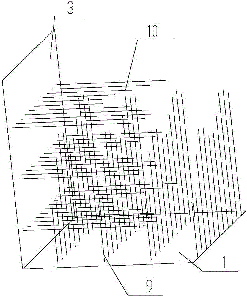
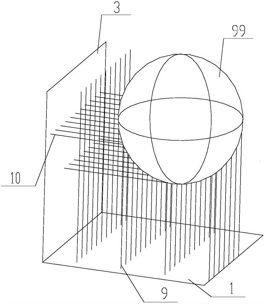
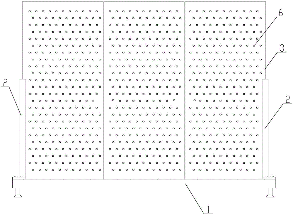
[0031] Please refer to Figure 1 to Figure 9 , figure 1 Schematic diagram of the structure of the supporting platform provided by the embodiment of the present invention; figure 2 for figure 1 Schematic diagram of the supporting pedestal supporting a spherical workpiece in ; image 3 for figure 1 The front view of the support stand when the first telescopic rod and the second telescopic rod are not set in Figure 4 for image 3 side view of Figure 5 for image 3 top...


PUM


Abstract

The invention discloses a supporting rack. The supporting rack comprises a positioning platform. The positioning platform is provided with a plurality of first telescopic rods capable of independently stretching and contracting so as to support a to-be-detected workpiece in the gravity direction. The supporting rack further comprises a plurality of second telescopic rods used for avoiding the relative position change between the to-be-detected workpiece and the positioning platform in the non-gravity direction in the contact detecting process. All the first telescopic rods are arranged in parallel, and all the second telescopic rods are arranged in parallel. The first telescopic rods are perpendicular to the ground, and the second telescopic rods are parallel to the ground. The invention further discloses a three-coordinate detecting instrument comprising the above supporting rack. According to the above supporting rack, the purpose of supporting most of to-be-detected workpieces with the complex surfaces is achieved, and universality is improved.

Description

technical field [0001] The invention relates to the technical field of detection instruments, in particular to a support stand. In addition, the present invention also relates to a three-coordinate detector with the support stand. Background technique [0002] With the continuous development of my country's machinery industry, the market demand for a three-coordinate detector with a support stand is increasing. [0003] At present, the existing three-coordinate detectors at home and abroad can be roughly divided into two categories: fixed detectors and portable detectors. The fixed detector has its built-in fixed platform and high accuracy, but the equipment has the disadvantages of bulky size and very expensive cost; The portable three-coordinate detector is a articulated arm rotating structure, which has the advantages of movable operation, wide versatility, and flexible operation. However, its fixed platform is simple, heavy, weak in versatility, and lacks multiple funct...

Claims


Application Information

Patent Timeline
IPC IPC(8): B25H1/14
CPCB25H1/14
Inventor 吴洁新何国志张成永
Owner BEIQI FOTON MOTOR CO LTD
Learn More