
A 3D printing method for side elevation dyeing

A 3D printing and side elevation technology, which is applied in the field of 3D printers and printer equipment, can solve the problems that the direction of ink drop penetration is not easy to control, cannot meet the requirements of side elevation dyeing, and the color of imaging points on the side elevation is missing, etc., to achieve printing Good dyeing effect, good application prospect, color controllable effect

Inactive Publication Date: 2017-11-17
朱沫
View PDF4 Cites 0 Cited by
  • Summary
  • Abstract
  • Description
  • Claims
  • Application Information

AI Technical Summary

Problems solved by technology

[0003] Compared with the published similar patent technologies, the domestic patent application 201410294525 and the patent application number 201410045626 both propose a method of inkjet with a vertical ink head moving in the horizontal direction to directly dye the upper surface of each layer of fusion layer, using the method of penetration The inkjet ink on the upper surface penetrates into the side elevation of the printing layer, so as to achieve the goal of displaying the image on the side elevation. However, the penetration direction of the ink droplets in this method is not easy to control, and it is easy to cause the color loss of the imaging point on the side elevation Or the density is too high, it is not easy to produce a clear image
There are other methods to directly inkjet dye the side elevation by spraying ink horizontally to the side of the printed object, but this method of lateral inkjet cannot dye the side elevation with more complex shapes or shaded positions, so it is also Unable to meet all side elevation staining requirements
In addition, since the ink drop is printed close to the edge of the printing layer, and the edge is not completely horizontal, the ink drop may splash on the outer surface of the printed object layer, thereby causing secondary pigment pollution and affecting the appearance of the finished product

Method used


Image

  • A 3D printing method for side elevation dyeing
  • A 3D printing method for side elevation dyeing
  • A 3D printing method for side elevation dyeing

Examples


Embodiment 1

[0067] The color three-dimensional printer shown in this embodiment is a triangular columnar 3D printer. For the specific structure, please refer to the appendix of the instruction manual. Figure 5 Shown:

[0068] Including color ink cartridge 4, frame 5, movable platform 6, high-permeability filament extrusion head 7, low-permeability filament extrusion head 8, color ink nozzle 9, loading platform 10, base 11, high-permeability material Silk storage box 13, low-permeability material filament storage box 15 and corresponding conduit 14, the frame of triangular columnar 3D printer is installed on the base, and a liftable loading platform 10 is installed at the lower end of the inside of the frame. A movable platform 6 is driven and installed in the frame above the platform, and the lower end of the movable platform is respectively equipped with a high-permeability filament extrusion head 7, a low-permeability filament extrusion head 8, and a color ink nozzle 9, and a high-perm...

Embodiment 2

[0076] The color three-dimensional printer shown in this embodiment is a kind of XYZ three-axis three-axis three-dimensional printer. Image 6 Shown:

[0077] It includes a movable platform 6, a high-permeability filament extrusion head 7, a low-permeability filament extrusion head 8, a color ink nozzle 9, a loading platform 10 and a base 19, and the loading platform 10 is installed in the middle of the base. The platform is used to carry 3D printed objects. Z-axis columns 18 are fixed vertically at the four corners of the base on the outer periphery of the platform, and a Y-axis slideway 17 is fixed horizontally at the upper ends of the Z-axis slides on the left and right sides. 1. An X-axis slideway 16 is installed for horizontal movement between the Y-axis slideways on the right sides, and the X-axis slideway can move along the Y-axis slideway; a movable platform 6 is installed on the X-axis slideway, which can The mobile platform can move along the X-axis guideway;

[00...


PUM


Abstract

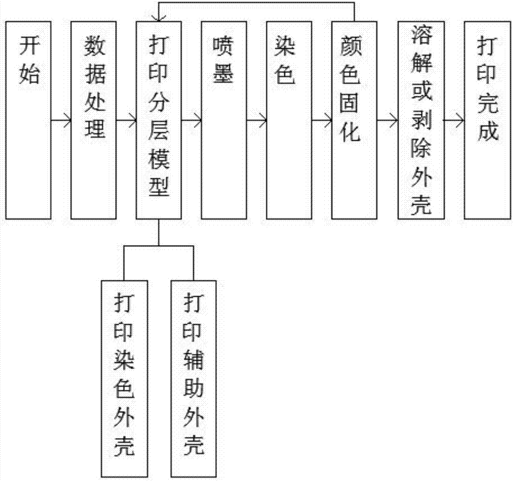
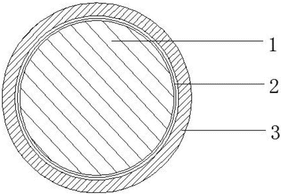
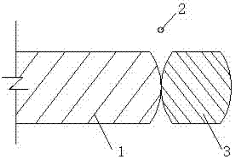
The invention relates to a 3D printing method for dyeing of a lateral vertical surface. The 3D printing method for dyeing of the lateral vertical surface comprises the following steps that (1) printing preparation and data processing are conducted, specifically, a vertical color printer is started, and processing is conduced, so that a hierarchical model of a 3D printed object is obtained; (2) the hierarchical model is printed, and an arc-shaped crack is formed between a dyed shell and an auxiliary shell; (3) ink jetting is conducted, and the printer is controlled by a processor to drip pigment ink into the arc-shaped crack formed between the dyed shell and the auxiliary shell; (4) dyeing is conducted; (5) color curing is conducted; (6) the next working cycle is conducted, and printing is conducted on the dyed shell subjected to dyeing and the auxiliary shell, so that the next hierarchical model is generated; (7) the shells are dissolved or stripped; and (8) printing is completed, after printing of all hierarchical models and dyeing are completed, the auxiliary shell is removed, the dyed lateral vertical outer surface of the 3D printed object is exposed, and the colored 3D printed object is obtained. The printing method is easy to implement, both the manufacturing cost of printing equipment and the manufacturing cost of printing materials are low, the printing effect is good, the application range is wide, and the 3D printing method has good application prospects.

Description

technical field [0001] The invention relates to the technical field of printer equipment, in particular to the technical field of 3D printers, and specifically refers to a 3D printing method for side elevation dyeing. Background technique [0002] At present, the rapid prototyping technology on the market is divided into 3DP technology and FDM fusion lamination molding technology. The objects obtained by these printing methods have only a small number of colors, and there are defects of poor colors. [0003] Compared with the published similar patent technologies, the domestic patent application 201410294525 and the patent application number 201410045626 both propose a method of inkjet with a vertical ink head moving in the horizontal direction to directly dye the upper surface of each layer of fusion layer, using the method of penetration The inkjet ink on the upper surface penetrates into the side elevation of the printing layer, so as to achieve the goal of displaying the...

Claims


Application Information

Patent Timeline
Patent Type & Authority Patents(China)
IPC IPC(8): B29C64/379B41M5/00B33Y40/00
CPCB33Y40/00B41M5/0088
Inventor 朱沫张伟丽
Owner 朱沫
Learn More