
Concise umbrella hanging rack

An umbrella and concise technology, applied in the field of racks, can solve problems such as inappropriate installation and hidden dangers to students' personal safety, and achieve the effect of eliminating hidden dangers, good adaptability and good concealment.

Active Publication Date: 2016-07-27
孙毅
View PDF8 Cites 1 Cited by
  • Summary
  • Abstract
  • Description
  • Claims
  • Application Information

AI Technical Summary

Problems solved by technology

[0003] Umbrella racks are the basic configuration items for classrooms in primary and secondary schools. Because some school classroom corridor windowsill planes are not suitable for installation, that is, they can only be installed on the facade of classroom corridor walls, and its 2 or 4 metal piles and nails protrude from the wall. There is a certain degree of hidden danger to the personal safety of students

Method used


Image

  • Concise umbrella hanging rack
  • Concise umbrella hanging rack
  • Concise umbrella hanging rack

Examples


Embodiment 1

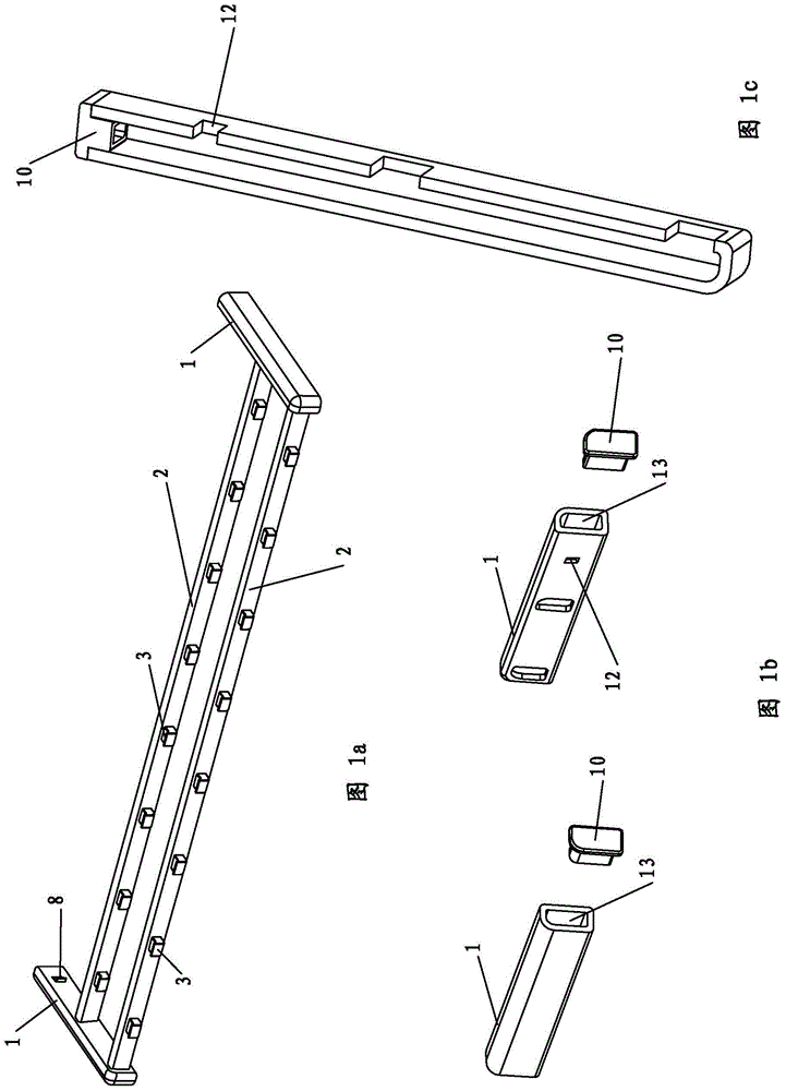
[0032] Example 1. see Figure 1a and Figure 1b : the hanging frame body is structured by vertically connecting crossbars (2) between two parallel end arm pipes (1), and the crossbars (2) are provided with series pile heads (3) for hanging umbrellas (compared with Figure 1a and Figure 4a -b can be seen: the direction of the series of pile heads (3) on the cross bar (2) can have different arrangements). The opposite sides of the two end arm pipes (1) are symmetrically provided with bolt openings (12). The end arm tube (1) is provided with a rear port (13), and after the guide seat (5), compression spring (6), and bolt pad (7) are loaded into the end arm tube (1), the rear cover (10) Closed, the hanging frame achieves a neat appearance.

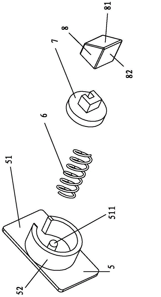
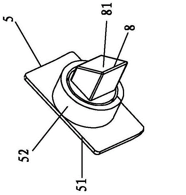
[0033] see Figure 1c and Figure 2a -d: Each end arm tube (1) is equipped with a locking control system composed of a guide seat (5), a compression spring (6), a bolt pad (7) and a bolt cap (8). The locks on the left and right sides Th...

Embodiment 2

[0039] Example 2. Only the one-sided end arm tube (1) contains a bolt port (12) and a lock control system consisting of a bolt pad (7), a compression spring (6), a guide seat (5), and a bolt cap (8). Compared with Embodiment 1, although the actual force is asymmetrical, the reliable insertion of the hanging frame in the middle hole (411) of the left and right sockets (4) can still be completed.

[0040] In this example, although the lock control system can only exist on one side of the end arm tube (1), and can still complete the centralized hanging and placing of umbrellas in a collective environment, it exists symmetrically on the left and right end arm tubes (1). A locking system is preferred.

[0041] Continue to explain this design below:

[0042] 1. the bolt mouth (12) is not limited to the opposite faces of the left and right end arm pipes (1), but is most suitable for the opposite faces of the left and right end arm pipes (1).

[0043] ②Obviously, the structure of t...


PUM


Abstract

The invention discloses a concise umbrella hanging rack, and relates to a storage rack applied to a collective place. Bolt openings are formed in the side faces of end arm pipes of a hanging frame, and a locking control system, which is composed of a guide base, a compression spring, a bolt pad and a bolt cap, is borne on each of the end arm pipes; two sockets, which are provided with median holes, are fixed to a wall facade by an equal height; inclined plates are arranged on the sides of empty regions in the median holes; and since the locking control systems are matched with the empty regions and the inclined pressing plates, the hanging frame is under a state of hanging umbrellas in a horizontal direction when the left and right end arm pipes of the hanging frame are inserted in the median holes of the left and right sockets. According to the design, the locking control system is good in hiding property and detaching-resistant; and the locking control system has the property of being semi-automatic to use and unlock, and the locking effect of the locking control system can achieve a requirement of practical use, so that safety hidden troubles in previous similar designs are eliminated.

Description

technical field [0001] The invention relates to a storage rack used in collective places, namely a simple umbrella hanging rack. Background technique [0002] The idea of ​​Chinese patent 201120069987.4 (classroom umbrella centralized hanging rack) is: at the appropriate height of the classroom corridor window sill plane or corridor wall facade, the nail bodies of 2 piles are deep into the wall and fixed (high-strength chemical anchoring ); the hanging frame is structured by a cross bar vertically connected between two parallel end arms. A series of stakes for hanging umbrellas are arranged on the cross bar. There is a hole slightly larger than the peg cap; when the holes on the two end arms (tubes) are buckled on the neck of the peg, the peg cap is pressed against the periphery of the hole to prevent the end arms from falling off from the peg, that is, the hanging frame The hooking state on the two pegs is stable; when the umbrella hanging rack is not in use in non-rainy w...

Claims


Application Information

Patent Timeline
IPC IPC(8): A47G25/12
Inventor 孙毅
Owner 孙毅
Learn More