Concealed positioning and bearing structure of device

A concealed and device technology, applied in furniture parts, garbage collection, household appliances, etc., can solve the problems of poor storage stability and low space utilization of utensils, avoid fixed size of drawers, improve storage stability, and improve The effect of using the experience

Pending Publication Date: 2021-01-12
GUANGDONG DTC HARDWARE PRECISION MFG CO LTD
View PDF1 Cites 1 Cited by
  • Summary
  • Abstract
  • Description
  • Claims
  • Application Information

AI Technical Summary

Problems solved by technology

[0003] The purpose of the present invention is to provide a concealed positioning and storage structure for devices, so as to overcome the fixed size of the drawer in the prior art, which can only accommodate a single-sized container, low space utilization rate, and poor storage stability of the container inadequacies of

Method used


Image

  • Concealed positioning and bearing structure of device
  • Concealed positioning and bearing structure of device
  • Concealed positioning and bearing structure of device

Examples


no. 1 example

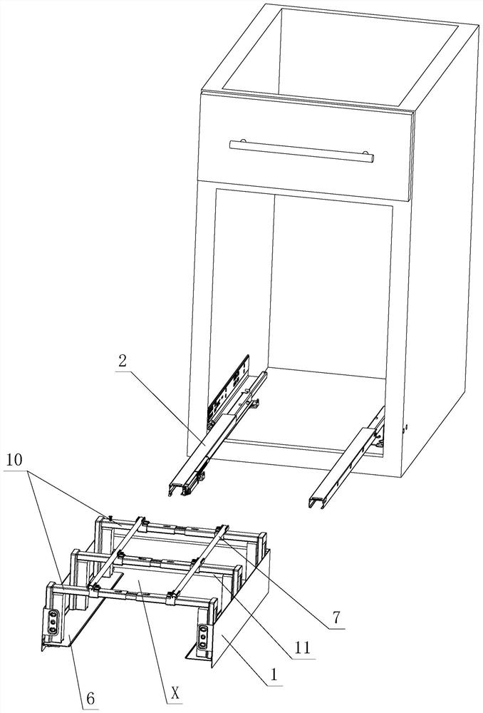
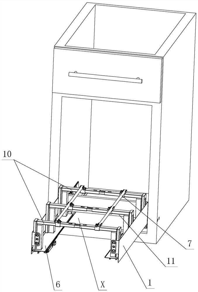
[0038] see Figure 1-Figure 10 , the hidden positioning and receiving structure of this device includes side plates 1 and slide rail assemblies 2 arranged on the left and right, support parts 4 are respectively provided on the lower parts of the left and right side plates 1, and support parts 5 are respectively provided on the left and right support parts 4; The side plate 1 is detachably installed on the slide rail assembly 2, and when the two are assembled, the slide rail assembly 2 leans against the inner side of the relying part 5; a receiving device is arranged between the left and right supporting parts 4, and the bearing The release device includes a cross-bar telescopic assembly and a left and right base 6, and the left and right bases 6 are respectively supported on the left and right support parts 4 and / or the left and right slide rail assemblies 2; the cross-bar telescopic assembly is fixed and / or The vertical movement is between the left and right bases 6, and ther...

no. 2 example

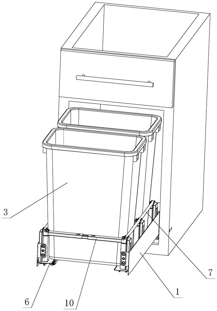
[0053] see Figure 11-Figure 13 , the concealed positioning and receiving structure of the device is different from the first embodiment in that: when the device 3 is placed in the receiving area X, the two sides of the bottom of the device directly act on the left and right slide rail assemblies 2 respectively.

[0054] Other unmentioned parts are the same as the first embodiment.


PUM


Abstract

A concealed positioning and bearing structure of a device comprises a left side plate, a right side plate, a left sliding rail assembly and a right sliding rail assembly, supporting parts are arrangedon the lower portions of the left side plate and the right side plate respectively, and leaning parts are arranged on the left supporting part and the right supporting part respectively; the side plates are detachably arranged on the sliding rail assemblies, and the sliding rail assemblies lean against the inner side of the leaning parts; a bearing device is arranged between the left supporting part and the right supporting part and comprises a transverse rod telescopic assembly and bases arranged on the left side and the right side, and the left base and the right base are supported on the left supporting part and the right supporting part and/or the left sliding rail assembly and the right sliding rail assembly respectively; the transverse rod telescopic assembly is fixed and/or longitudinally moves between the left base and the right base, a longitudinal rod transversely moves on the transverse rod telescopic assembly, and when the transverse rod telescopic assembly and the longitudinal rod move, at least one containing device and a bearing area with the adjustable longitudinal and/or transverse size are/is formed between the transverse rod telescopic assembly and the longitudinal rod; and devices are placed on the bearing area, the side portions of the devices are located on the transverse rod telescopic assembly and/or the longitudinal rods, and the two sides of the bottoms of the devices are located on the left base and the right base and/or the left sliding rail assembly and the right sliding rail assembly respectively.

Description

technical field [0001] The invention relates to a concealed positioning and storage structure for devices, in particular to a structure which is applied to drawers and can carry out concealed positioning and storage of devices. Background technique [0002] The Chinese patent document number is CN111086803A, which discloses a drawer-type concealed trash can on May 1, 2020, which includes a trash can, a flat panel, a drawer guide rail and a connecting device, and the connecting device is either an L-shaped corner code or a wooden strip. It is said that the above-mentioned structure combines the trash can, flat panel and drawer guide rails into one. Usually the trash can is hidden in the vacant space under the furniture floor, and it is pulled out when it is needed, which eliminates the stumbling and unsightlyness of the trash can placed in the room Two big disadvantages; however, the size of the space in the kitchen is different, and the size of the drawers is designed accor...

Claims


Application Information

Patent Timeline
Patent Type & Authority Applications(China)
IPC IPC(8): A47B88/40A47B88/407A47B88/90A47B88/919B65F1/14
CPCA47B2210/09A47B88/40A47B88/407A47B88/90A47B88/919A47B88/941B65F1/141
Inventor 伍志勇
Owner GUANGDONG DTC HARDWARE PRECISION MFG CO LTD
Why Eureka
Try Eureka