
Air conditioning system and control method thereof

An air-conditioning system and control method technology, applied in refrigerators, refrigeration and liquefaction, compressors with multiple condensers, etc., can solve problems such as wasting electric energy, large fluctuations in indoor temperature and humidity, and thermal load changes

Active Publication Date: 2016-07-27
GD MIDEA HEATING & VENTILATING EQUIP CO LTD +1
View PDF5 Cites 1 Cited by
  • Summary
  • Abstract
  • Description
  • Claims
  • Application Information

AI Technical Summary

Problems solved by technology

[0002] In related technologies, due to the particularity of the computer room, the air conditioning system in the computer room must run continuously for a long time to meet the special needs. Generally, two units are always prepared for active and standby switching. However, in practical applications, the use of standby units is seldom. Due to the possible start and stop of some servers in the computer room, the thermal load changes, and the slow response of the unit will lead to large fluctuations in indoor temperature and humidity
In addition, in the case of high humidity and low heat in the early stage of computer room construction, ordinary units need to waste a lot of power in the dehumidification process

Method used


Image

  • Air conditioning system and control method thereof
  • Air conditioning system and control method thereof

Examples


Embodiment Construction

[0038] Embodiments of the present invention are described in detail below, examples of which are shown in the drawings, wherein the same or similar reference numerals denote the same or similar elements or elements having the same or similar functions throughout. The embodiments described below by referring to the figures are exemplary only for explaining the present invention and should not be construed as limiting the present invention.

[0039] In the description of the present invention, it should be understood that the terms "first" and "second" are used for description purposes only, and cannot be interpreted as indicating or implying relative importance or implicitly indicating the quantity of indicated technical features. Thus, a feature defined as "first" or "second" may explicitly or implicitly include one or more of said features. In the description of the present invention, "plurality" means two or more, unless otherwise specifically defined.

[0040] In the descr...


PUM


Abstract

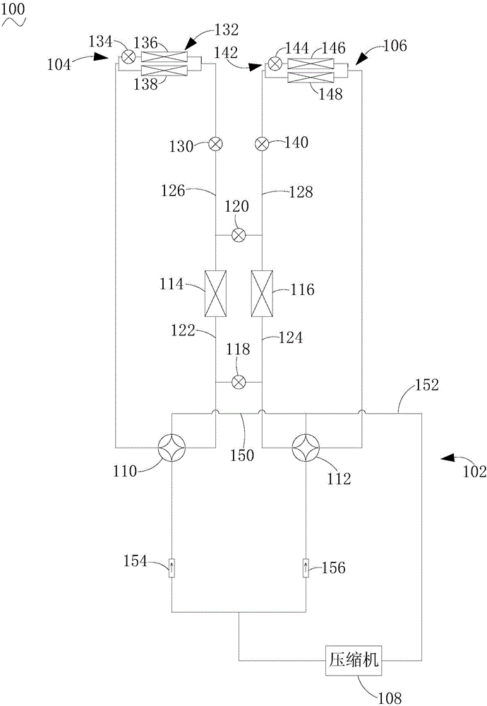
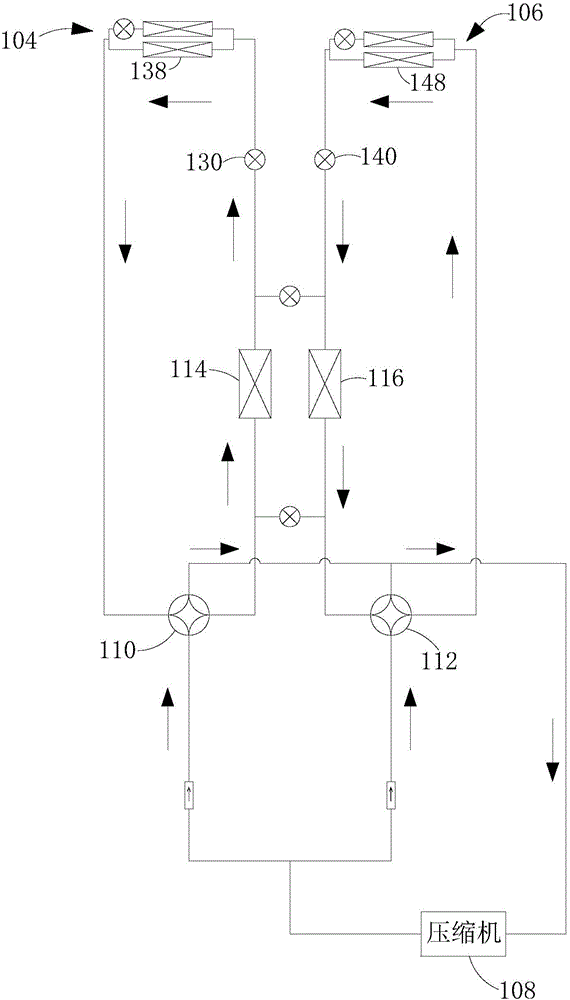
The invention discloses an air conditioning system. In the air conditioning system, a compressor, a first reversing valve, a first heat exchanger and a first indoor unit are connected to form a first circulation pipeline; the compressor, a second reversing valve, a second heat exchanger and a second indoor unit are connected to form a second circulation pipeline; the first circulation pipeline comprises a first pipeline, a second pipeline, a third pipeline and a fourth pipeline, wherein the first pipeline is used for connecting the first reversing valve with the first heat exchanger; the second pipeline is used for connecting the second reversing valve with the second heat exchanger; the third pipeline is used for connecting the first heat exchanger with the first indoor unit; the fourth pipeline is used for connecting the second heat exchanger with the second indoor unit; a first valve body is used for connecting the first pipeline with the second pipeline; a second valve body is used for connecting the third pipeline with the fourth pipeline. The air conditioning system is capable of making the first indoor unit and the second indoor unit to work at the same time or work at different time by utilizing the first circulation pipeline and the second circulation pipeline; the first valve body and the second valve body are capable of making the first heat exchanger and the second heat exchanger to support the work of one indoor unit at the same time, so that the refrigeration capability of the air conditioning system is guaranteed. The invention also discloses a control method of the air conditioning system.

Description

technical field [0001] The present invention relates to the field of air conditioning, and more specifically, to an air conditioning system and a control method for the air conditioning system. Background technique [0002] In related technologies, due to the particularity of the computer room, the air conditioning system in the computer room must run continuously for a long time to meet the special needs. Generally, two units are always prepared for active and standby switching. Due to the possible start and stop of some servers in the computer room, the heat load changes, and when the response of the unit is slow, the indoor temperature and humidity fluctuate greatly. In addition, in the case of high humidity and low heat in the early stage of computer room construction, ordinary units need to waste a lot of electric energy in the dehumidification process. Contents of the invention [0003] The embodiments of the present invention aim to solve at least one of the techni...

Claims


Application Information

Patent Timeline
Patent Type & Authority Applications(China)
IPC IPC(8): F25B5/02F25B6/02
CPCF25B5/02F25B6/02F25B2313/02331F25B2313/02521
Inventor 雷海涛陈乾
Owner GD MIDEA HEATING & VENTILATING EQUIP CO LTD
Learn More