Tail heat recovery steam plate dryer

A flat-plate dryer and exhaust heat recovery technology, applied in the direction of dryers, drying solid materials, drying gas arrangement, etc., can solve problems such as difficulty in disassembly, achieve the effects of eliminating fatigue fractures, saving materials, and achieving remarkable results

Active Publication Date: 2018-07-03
JIANGSU ZHONGLI PETROCHEM EQUIP
View PDF6 Cites 0 Cited by
  • Summary
  • Abstract
  • Description
  • Claims
  • Application Information

AI Technical Summary

Problems solved by technology

In the actual assembly of shafts and holes with transmission threads, in order to achieve large load-bearing functions, the size of the threaded shafts and matching nut-like components are relatively large, and it is often easy and convenient to screw in during assembly, and It can realize the automatic and continuous locking of the bearing capacity during use, so it is very reliable, but when it is disassembled, the assembly is often very tight, and disassembly is very difficult. It is particularly important to realize simple and easy disassembly under this condition

Method used


Image

  • Tail heat recovery steam plate dryer
  • Tail heat recovery steam plate dryer
  • Tail heat recovery steam plate dryer

Examples


Embodiment Construction

[0033] The present invention will be further described in detail with reference to the accompanying drawings.

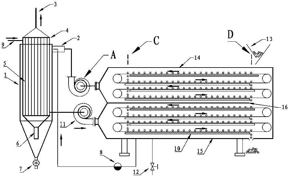
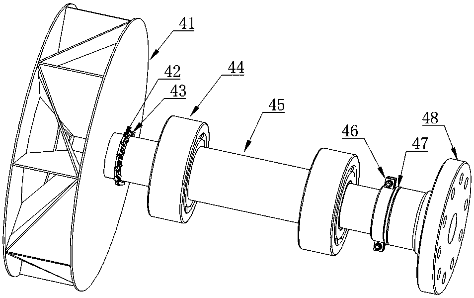
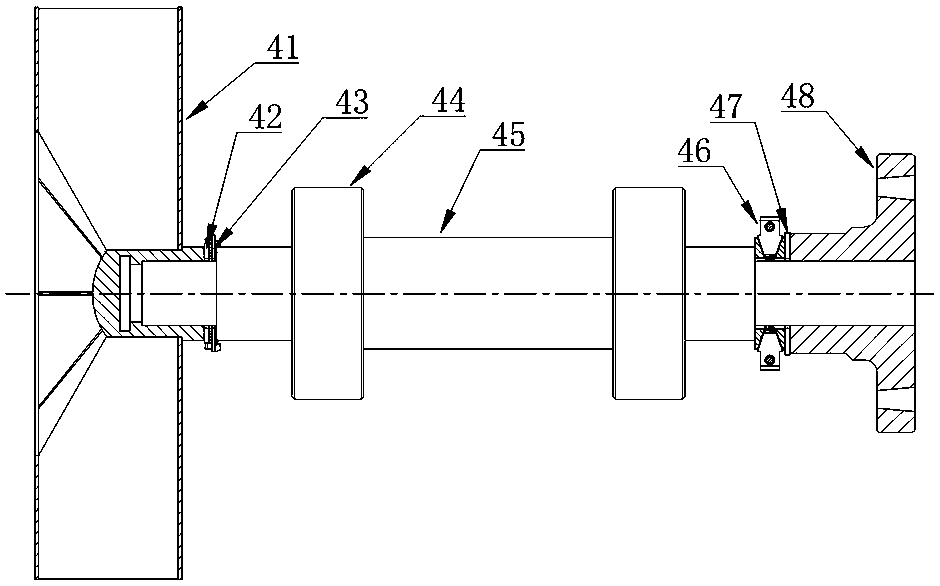
[0034] Such as figure 1 , figure 2 , image 3 , Figure 4 , Figure 5 , Image 6 , Figure 7 , Figure 8 with Picture 9 The tail heat recovery type steam plate dryer shown includes a dryer and an induced draft fan A. The dryer is equipped with a driving wheel, a passive wheel and a scraper to transport the animal material on the steam plate 10, and the steam plate 10 is connected to the steam valve 12 and the trap valve 8; There is a middle partition 16 in the dryer to divide the drying into an upper drying zone and a lower drying zone; the upper drying zone is tangentially connected by the induced draft fan A to the cyclone formed by the superposition of the tubular heat exchanger 4 and the cyclone dust collector 1 Dust removal tail heat high-efficiency recovery device, after cyclone dust removal, the dust is discharged through the closed air device 7 at the bottom o...


PUM


Abstract

The invention discloses a tail heat recovery type steam plate dryer. An upper drying area of the dryer is tangentially connected with a cyclone dust removal tail heat efficient recovery device through an induced draft fan, and a tube type heat exchanger and a cyclone dust remover are overlaid to form the cyclone dust removal tail heat efficient recovery device. After cyclone dust removal, dust is discharged at the cone bottom through an air-lock valve. Tail gas is connected with a cone body through a cyclone ascending pipe, penetrates through a tube nest after being evenly dispersed, and is exhausted through an exhaust pipe after being concentrated by an upper cone hopper. Blades of an impeller of the induced draft fan are arranged in the radial shape that the blades are centrosymmetric in the radial direction of an impeller shaft, and the dust can be removed through centrifugal force in time. According to the tail heat recovery type steam plate dryer, the drying efficiency is improved, and energy conservation and emission reduction are realized; more importantly, the dismounting technology of the induced draft fan is changed substantially, so that when the induced draft fan is dismounted, pressure of components like nuts on the end faces of screw shaft shoulders can be eliminated simply, the problem that the induced draft fan is constantly automatically locked and is difficult to dismount under the action of loads during threaded assembling is solved effectively, and the technology is especially suitable for conveniently dismounting a large fan locked through threads.

Description

Technical field [0001] The invention relates to a dryer, which specifically guides a tail heat recovery type steam flat plate dryer that does not accumulate dust and is convenient for disassembly and overhaul. Background technique [0002] Due to mature technology, strong adaptability, low energy consumption and strong reliability, the steam heating plate dryer has become one of the main preferred equipment for material drying. The materials are conveyed on the steam heating plate through the scraper for contact heating drying. Due to the simple structure, particularly low energy consumption, strong processing capacity, and each layer of the material is turned over, the quality of the dried product is particularly uniform and reliable. However, the drying process needs to continuously discharge damp and hot exhaust gas to promote the drying process. Since the exhaust gas is rich in exhaust heat, it is necessary to perform exhaust heat recovery operations on the exhaust gas. There...

Claims


Application Information

Patent Timeline
Patent Type & Authority Patents(China)
IPC IPC(8): F26B17/00F26B25/00F26B21/00F04D29/054F04D29/28F04D29/70
CPCF04D29/054F04D29/281F04D29/703F26B17/003F26B21/002F26B25/005F26B25/007Y02P70/10
Inventor 张旭银永忠张思言
Owner JIANGSU ZHONGLI PETROCHEM EQUIP
Why Eureka
Try Eureka