Supercharge Your Innovation With Domain-Expert AI Agents!

Current acquisition circuit of magnetizing power supply

A technology of acquisition circuit and power supply, which is applied in the field of current acquisition circuit, can solve the problems that the current acquisition circuit cannot meet the online measurement requirements, and achieve the effects of suppressing zero drift and noise interference, accurate measurement, and low cost

Active Publication Date: 2019-03-29
RES INST OF PHYSICAL & CHEM ENG OF NUCLEAR IND
View PDF6 Cites 0 Cited by
  • Summary
  • Abstract
  • Description
  • Claims
  • Application Information

AI Technical Summary

Problems solved by technology

However, the commonly used current acquisition circuit cannot meet the requirements of online measurement.

Method used


Image

  • Current acquisition circuit of magnetizing power supply

Examples


Embodiment Construction

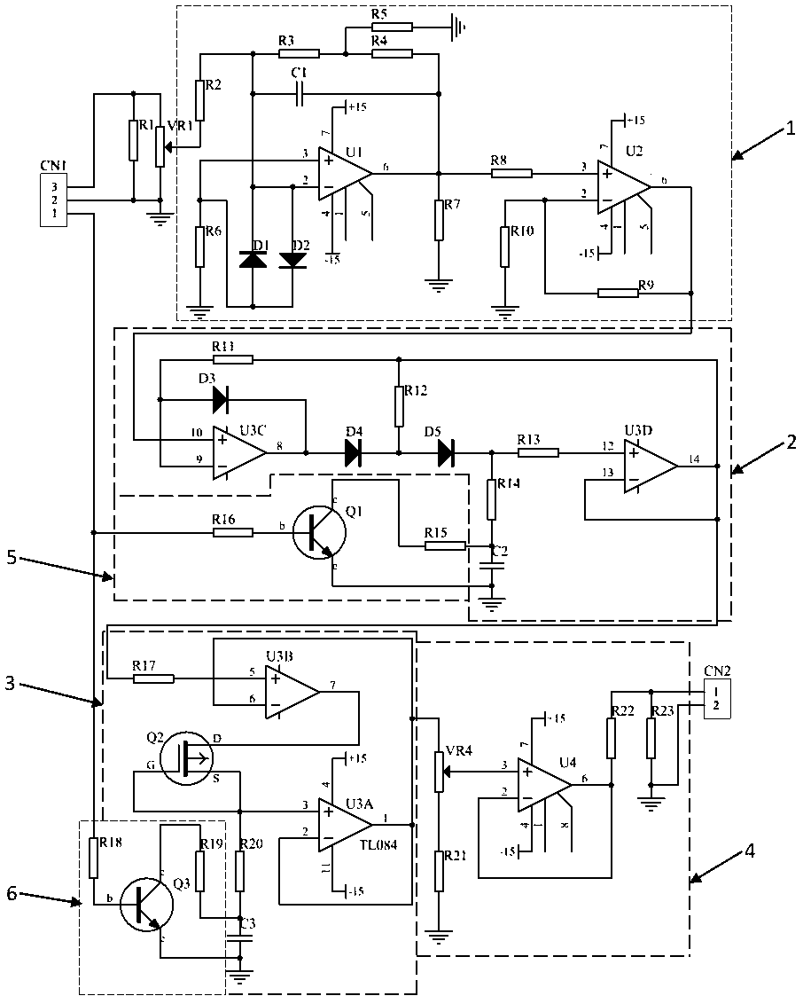
[0016] Below, the present invention is described in detail with reference to accompanying drawing and embodiment:

[0017] Such as figure 1 As shown, a current acquisition circuit of a magnetizing power supply includes a terminal CN1, a resistor R1 and a potentiometer VR1 are connected in parallel between the No. The amplifying circuit 1 is connected, the two-stage amplifying circuit 1 is connected to the signal holding circuit 2, the signal holding circuit 2 is connected to the amplifying circuit 3, the amplifying circuit 3 is connected to the signal output circuit 4, and the signal output circuit 4 is connected to the The connecting terminal CN2 is connected, and the No. 1 reset circuit 5 is set between the No. 1 pin of the connecting terminal CN1 and the signal holding circuit 2, and the No. Ⅱ reset circuit 5 is set between the No. 1 pin of the connecting terminal CN1 and the amplifying circuit 3. Reset circuit 6.

[0018] The two-stage amplifying circuit 1 includes an op...


PUM


Abstract

The invention relates to a current collecting circuit of a magnetizing power source.The current collecting circuit comprises a terminal CN1, and a resistor R1 and a potentiometer VR1 are connected between a second pin and a third pin of the terminal CN1 in parallel, and the potentiometer VR1 is connected with a two-stage amplifying circuit.The two-stage amplifying circuit is connected with a signal retaining circuit, the signal retaining circuit is connected with an amplifying circuit, and the amplifying circuit is connected with a signal output circuit.The signal output circuit is connected with a terminal CN2, a rest circuit I is arranged between a first pin of the terminal CN1 and the signal retaining circuit, and a reset circuit II is arranged between the first pin of the terminal CN1 and the amplifying circuit.The current collecting circuit can monitor discharge circuit with very short discharge time and very high instantaneous currents in real time, zero wander and noise interference can be inhibited, the discharge currents are accurately measured, manufacturing cost is low, and development cost can be greatly reduced.

Description

technical field [0001] The invention belongs to a collection circuit, in particular to a current collection circuit of a magnetized power supply. Background technique [0002] The magnetizing power supply adopts the pulse magnetic field magnetization method. Firstly, the alternating current is converted into direct current and stored in the capacitor, and then a large-capacity thyristor switch is used to discharge the capacitor instantaneously, and a strong pulse magnetic field is generated in the magnetizing coil to make the coil in the coil The magnet is magnetized. The capacitor pulse discharge time is very short (tens of milliseconds), and the instantaneous current is very large (thousands of amperes). It is necessary to monitor the discharge current at any time to ensure that the magnetizing power supply is in a normal working state. However, the commonly used current acquisition circuit cannot meet the online measurement requirements. Contents of the invention [0...

Claims


Application Information

Patent Timeline
Patent Type & Authority Patents(China)
IPC IPC(8): G01R19/00H03F3/21H03K17/22
CPCG01R19/0092H03F3/21H03K17/22
Inventor 于民东彭树文赵秋毅王麟
Owner RES INST OF PHYSICAL & CHEM ENG OF NUCLEAR IND
Features
  • R&D
  • Intellectual Property
  • Life Sciences
  • Materials
  • Tech Scout
  • Unparalleled Data Quality
  • Higher Quality Content
  • 60% Fewer Hallucinations
Learn More