Foldable electronic equipment

An electronic device and foldable technology, applied in electrical digital data processing, instruments, digital data processing components, etc., can solve the problems of cumbersome operation, increase user operation, reduce user experience, etc., achieve simple operation, simplify user operation, The effect of improving user experience

Active Publication Date: 2016-07-27
SUPERD CO LTD
View PDF5 Cites 10 Cited by
  • Summary
  • Abstract
  • Description
  • Claims
  • Application Information

AI Technical Summary

Problems solved by technology

[0003] That is to say, in the prior art, the operation when opening the electronic device is relatively cumbersome, and the upper cover of the electronic device needs to be manually flipped and opened, which is laborious and time-consuming, and the opening process cannot be completed in one step, which increases user operations and reduces user experience
At the same time, after turning on the electronic device, in order to switch the electronic device from the standby state to the running state, it is necessary to further press the power button, which further increases user operations and reduces user experience.

Method used


Image

  • Foldable electronic equipment
  • Foldable electronic equipment
  • Foldable electronic equipment

Examples


no. 1 example

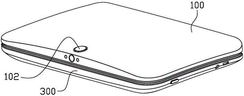
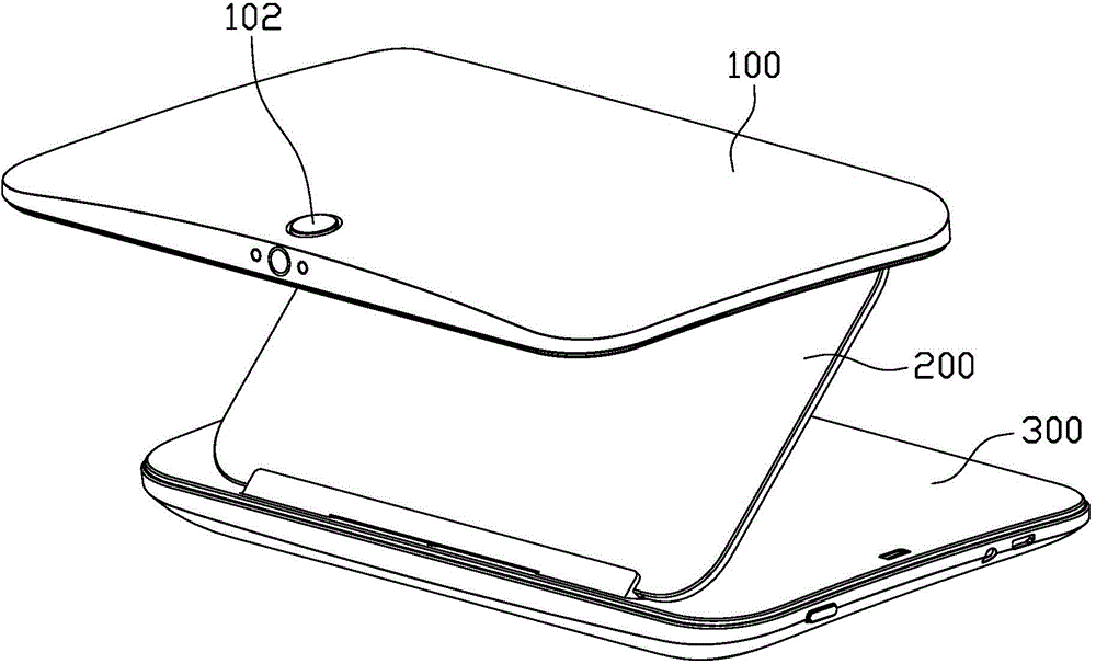
[0036] figure 1 It is a schematic diagram of the foldable electronic device in the closed state in the first embodiment of the present invention, figure 2 It is a schematic diagram of the foldable electronic device in the open state in the first embodiment of the present invention, please refer to figure 1 and figure 2 , the foldable electronic device includes a first cover 100 , a transflective assembly 200 and a second cover 300 . In this embodiment, the first cover 100 is the upper cover assembly of the foldable electronic device, and the second cover 300 is the lower cover assembly of the foldable electronic device, but it is not limited thereto. In other embodiments, the first A cover 100 can be used as a lower cover assembly of the foldable electronic device, and a second cover 300 can be used as an upper cover assembly of the foldable electronic device.

[0037] Such as figure 1 and figure 2 As shown, the structure of the foldable electronic device has two state...

no. 2 example

[0055] Figure 9 It is a schematic diagram of the foldable electronic device in the closed state in the second embodiment of the present invention, please refer to Figure 9 The difference between this embodiment and the first embodiment lies in the unlocking structure and unlocking method. Specifically, the unlock switch 302 is not arranged on the first cover 100, but on the second cover 300. The unlock switch 302 is, for example, a sliding switch, and the sliding unlock switch 302 is preferably arranged on the second cover 300. The side of the cover 300 is disposed adjacent to the lock bolt 303 and connected to the lock bolt 303 so that the sliding switch can drive the lock bolt 303 to move when it is toggled.

[0056] Figure 10 It is a schematic diagram of the buckle and the lock bolt in the second embodiment of the present invention when they are locked, Figure 11 It is a schematic diagram of the lock and the lock bolt in the second embodiment of the present invention...

no. 3 example

[0059] Figure 12 It is a schematic diagram of the foldable electronic device in the open state in the third embodiment of the present invention, Figure 13 It is a schematic diagram of the foldable electronic device in the closed state in the third embodiment of the present invention, please refer to Figure 12 and Figure 13 The difference between this embodiment and the first embodiment lies in the manner in which the foldable electronic device switches between the standby state and the running state. Specifically, the closure detection device includes a pressing rod 108 and a button 308, one of which is arranged on the first cover 100, and the other is arranged on the second cover 300, for example In this embodiment, the pressing rod body 108 is disposed on the first cover body 100 , and the button 308 is disposed on the second cover body 300 . Specifically, in this embodiment, the pressing rod body 108 protrudes from the first cover body 100 and faces the second cover ...


PUM


Abstract

The invention discloses foldable electronic equipment, which comprises a first cover body, a second cover body, an unlocking switch, a closing detection device and a processor, wherein the first cover body is connected with the second cover body through a movable connection structure and comprises a lock catch; the second cover body comprises a latch; the closing detection device is in signal connection with the processor; the electronic equipment has a closing state and an opening state, the closing detection device is used for detecting whether the electronic equipment is under the closing state or not; when the electronic equipment is under the closing state, the lock catch and the latch are tightly locked, the closing detection device detects that the electronic equipment is under the closing state, and the processor controls the electronic equipment to be under a standby state; when the unlocking switch is operated, the lock catch and the latch are unlocked, the electronic equipment automatically pops to the opening state from the closing state under the function of the movable connection structure, and when the closing detection device detects that the electronic equipment is under a non-closing state, the processor controls the electronic equipment to automatically switch to an operation state from the standby state.

Description

technical field [0001] The invention relates to the technical field of electronic equipment, in particular to a foldable electronic equipment. Background technique [0002] In the prior art, when opening an electronic device, such as a notebook computer, the common method is: manually open the cover structure of the notebook computer, so that the power button of the notebook computer is exposed; then, the user manually activates the power button of the notebook computer, So that the notebook computer is powered on and enters the running state. When the user does not want to use the notebook computer at this time, usually the cover structure of the notebook computer can be pressed down, so that the notebook computer is in a standby state to save power. When the user wants to use the notebook computer again, the user needs to open the cover structure of the notebook computer first, and then press the power button of the notebook computer, so that the notebook computer enters ...

Claims


Application Information

Patent Timeline
Patent Type & Authority Applications(China)
IPC IPC(8): G06F1/16
Inventor 曾志荣童水波赖金石潘铭贤班起
Owner SUPERD CO LTD
Why Eureka
Try Eureka